 Triumph Scrambler 1200 XC - Service manual > Introduction
This manual is designed primarily for use by trained technicians in a properly equipped workshop. However, it contains enough detail and basic information to make it useful to the owner who desires to perform his own basic maintenance and repair work. The work can only be carried out if the owner has the necessary hand and special service tools to complete the job.
A basic knowledge of mechanics, including the proper use of tools and workshop procedures is necessary in order to carry out maintenance and repair work satisfactorily. Whenever the owner has insufficient experience or doubts regarding his ability to do the work, an authorised Triumph dealer must undertake all adjustments, maintenance, and repair work.
In order to perform the work efficiently and to avoid costly mistakes, read the text and thoroughly familiarise yourself with procedures before starting work.
All work should be performed with great care and in a clean working area with adequate lighting.
Always use the correct special service tools or equipment specified. Under no circumstances use makeshift tools or equipment since the use of substitutes may adversely affect safe operation.
Where accurate measurements are required, they can only be made using calibrated, precision instruments.
For the duration of the warranty period, an authorised Triumph dealer must perform all repairs and scheduled maintenance.
To maximise the life of your motorcycle:
- Accurately follow the maintenance requirements of the periodic maintenance chart in the Service Manual.
- Do not allow problems to develop. Investigate unusual noises and changes in the riding characteristics of the motorcycle. Rectify all problems as soon as possible (immediately if safety related).
- Use only genuine Triumph parts as listed in the electronic parts catalogue (EPC).
- Follow the procedures in this manual carefully and completely. Do not take short cuts.
- Keep complete records of all maintenance and repairs with dates and any new parts installed.
- Use only approved lubricants, as specified in the Owner's Handbook, in the maintenance of the motorcycle.
How to use this manual
To assist in the use of this manual, the section title is given at the top.
Each major section starts with a contents page, listing the information contained in the section.
The individual steps comprising repair operations are to be followed in the sequence in which they appear.
Adjustment and repair operations include reference to service tool numbers and the associated illustration depicts the tool.
Where usage is not obvious, the tool is shown in use.
Adjustment and repair operations also include reference to wear limits, relevant data, torque figures, specialist information and useful assembly details.
Warnings, Cautions and Notes
Particularly important information is presented in the following form:
WARNING
This warning symbol identifies special instructions or procedures which, if not correctly followed, could result in personal injury, or loss of life.
CAUTION
This caution symbol identifies special instructions or procedures which, if not strictly observed, could result in damage to or destruction of equipment.
Note
This note symbol indicates points of particular interest for more efficient and convenient operation.
Tampering with Noise Control System Prohibited
Owners are warned that the law may prohibit:
- The removal or rendering inoperative by any person other than for purposes of maintenance, repair or replacement, of any device or element of design incorporated into any new vehicle for the purpose of noise control prior to its sale or delivery to the ultimate purchaser or while it is in use; and
- The use of the vehicle after such device or element of design has been removed or rendered inoperative by any person.
References
References to the left hand or right hand side given in this manual are made when viewing the motorcycle from the rear.
Operations covered in this manual do not always include reference to testing the motorcycle after repair. It is essential that work is inspected and tested after completion and, if necessary, a road test of the motorcycle is carried out particularly where safety related items are concerned.
Dimensions
The dimensions quoted are to design engineering specification with service limits where applicable.
During the period of running-in from new, certain adjustments may vary from the specification figures given in this manual. These will be reset by the dealer at the 500 mile/800 km service, and thereafter should be maintained at the figures specified in this manual.
Repairs and Replacements
Before removal and disassembly, thoroughly clean the motorcycle. Any dirt entering the engine or other parts will work as an abrasive and shorten the life of the motorcycle. Particular attention should be paid when installing a new part, that any dust or metal filings are cleared from the immediate area.
Force
Common sense should dictate how much force is necessary in assembly and disassembly. If a part seems especially difficult to remove or install, stop and examine what may be causing the problem. Never lever a component as this will cause damage both to the component itself and to the surface being levered against.
Whenever tapping to aid removal of an item is necessary, tap lightly using a hide or plastic faced mallet.
Edges
Watch for sharp edges, especially during engine disassembly and assembly. Protect the hands with industrial quality gloves.
When replacement parts are required, it is essential that only genuine Triumph parts are used.
Safety features and corrosion prevention treatments embodied in the motorcycle may be impaired if parts other than genuine Triumph parts are fitted. In certain territories, legislation prohibits the fitting of parts not to the manufacturer's specification.
Tightening procedure
Generally, when installing a part with several bolts, nuts or screws, they should all be started in their holes and tightened to a snug fit, evenly and in a cross pattern. This is to avoid distortion of the part and/or gas or oil leakage. Conversely, bolts, nuts, or screws, should all be loosened (in sequence if specified) by about a quarter of a turn and then removed.
Where there is a tightening sequence specified in this Service Manual, the bolts, nuts, or screws must be tightened in the order and by the method indicated.
Torque wrench setting figures given in this manual must be observed. The torque tools used must be of accurate calibration.
Torque Tolerance
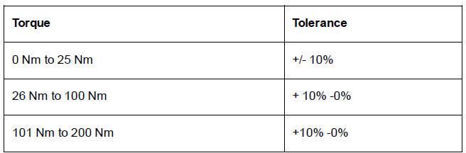
Locking devices, where specified, must be fitted. If the efficiency of a locking device is impaired during removal it must be renewed. This applies particularly to microencapsulated fixings which must always be replaced if disturbed. Where necessary, the text in this manual will indicate where such a fixing is used.
Use of Crow Foot Spanner Adapters with Torque Wrenches
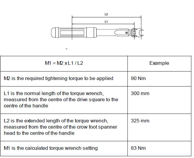
The use of a crow foot spanner adapter will effectively lengthen the lever arm of a torque wrench. The amount of torque applied to a fastener is increased as the torque wrench lever arm is extended, therefore the torque wrench setting must be adjusted in order to achieve the correct tightening torque.
Before tightening a fixing using a crow foot spanner adapter, measure the normal length of the torque wrench from the centre of the drive square to the centre of the handle (dimension L1). Fit the crow foot spanner adapter to the torque wrench as shown below. Measure the extended length of the torque wrench from the centre of the crow foot spanner head to the centre of the handle (dimension L2).
Use the following formula to calculate the correct torque wrench setting to achieve the required tightening torque.
Note
- The example shown below is calculated using a crow foot spanner measuring 25 mm from the centre of the spanner head to the centre of the drive square.

 Ducati Scrambler
 Fantic Caballero 500
 Indian FTR 1200
 Moto Guzzi V85 TT
 Royal Enfield Bullet Trials Works Replica
 Triumph Scrambler 1200 XE
 Triumph Street Scrambler
 Yamaha XSR700
 Ducati Scrambler 800
 Moto Guzzi V85 TT
 Triumph Scrambler 1200 XC