 Moto Guzzi V85 TT - Service manual > Operating diagram
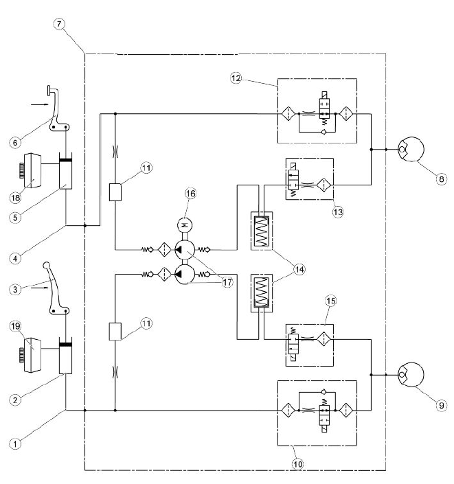
ABS functional diagram key
- Front system circuit
- Front brake master cylinder
- Front brake control lever
- Rear system circuit
- Rear brake pump
- Rear brake pedal control
- ABS control unit
- Rear brake calliper
- Front calliper (2 callipers)
- Front brake circuit intake solenoid valve (normally open)
- Humidifier
- Rear brake circuit intake solenoid valve (normally open)
- Rear brake exhaust circuit solenoid valve (normally closed)
- Rear/front brake circuit low pressure accumulator
- Front brake exhaust circuit solenoid valve (normally closed)
- DC electric motor
- Double circuit hydraulic pump (ABS)
- Rear brake reservoir
- Front brake reservoir
ABS OPERATION
General specifications:
The front circuit is the same as the rear one.
- The ABS inlet valve (10 - 12) is normally open and it is closed only when the system intervenes to avoid wheel locking.
- The exhaust valve (13 - 15) is normally closed and it is opened only when the system intervenes to avoid wheel locking.
- With the system in stand-by mode, the ABS processor controls the wheel speed instant by instant to assess any slippage of the wheels.
- When in standby, the system does not intervene at all when the rider brakes; the braking system is the same as the one without ABS.
ABS Cycle phases (the following operations refer to the front circuit but they are also valid for the rear):
A - Brake activation: the rider starts braking as he would usually do.
B - Pressure reduction: coincides with the recognition of the dangerous situation (wheel slippage exceeds the threshold): the system closes the inlet valve (10-12) and opens the exhaust valve (13-15) temporarily.
At this stage the rider cannot increase the pressure on the callipers (8-9) and the system reduces the pressure on the callipers partially. The excess fluid temporarily fills the front reservoir (18-19) until the ABS pump (17) self-activates and delivers the fluid back to the brake pump (2-5).
C - Maintaining pressure: the pressure in the callipers (8-9) remains low until total recovery of speed / wheel grip.
The system restores the fluid taken from the calliper (8-9) in the section of the system between the brake pump (2-5) and the ABS inlet valve (10-12).
D - Pressure restoration: by opening the inlet valve (10-12) momentarily, the pressure of the callipers (8-9) is increased until maximum deceleration is reached. Then, the system gives the control over the braking back to the rider.
E - If the wheel does not reach complete grip, the system continues operating as before until complete grip is obtained or until the vehicle stops. An error may be shown in the event that the duration of the pressure reduction phase exceeds a predetermined time limit.
ABS SYSTEM DESCRIPTION
The ABS system is a device to avoid wheels locking in case of emergency braking, increasing vehicle braking stability when compared to a traditional braking system.
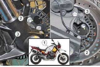
Sometimes when the brake is operated, the tyre locks with a consequent loss of grip, which makes it difficult to control the vehicle. A position sensor (3) on the tone wheel (2), forming an integral unit with the vehicle wheel, "reads" the status of the vehicle wheel spotting any possible lock.
A control unit (1) signals this out and adjusts the pressure in the braking circuit accordingly.
NOTE WHEN THE ABS STARTS WORKING, A PULSING IS FELT ON THE BRAKE LEVER.
THE WHEEL ANTILOCK BRAKING SYSTEM DOES NOT PREVENT FALLS WHILE ON A BEND. AN EMERGENCY BRAKING WITH THE VEHICLE INCLINED, HANDLE BAR TURNED, ON UNEVEN OR SLIPPERY ROADS, OR WITH POOR GRIP CREATES LACK OF STABILITY DIFFICULT TO HANDLE. THEREFORE, RIDE CAREFULLY AND SENSIBLY AND ALWAYS BRAKE GRADUALLY. BRAKING WHILE TURNING A CORNER IS SUBJECT TO LAWS OF PHYSICS WHICH NOT EVEN ABS CAN ELIMINATE.
When the sensors (3) detect a significant speed difference between the rear and the front wheels (for example, when rearing up on the back wheel), the ABS system could take this as a dangerous situation.
In this case, there are two possible results:
- The ABS system intervenes by releasing pressure from the calliper until the wheel turns again at the same speed of the other wheel. It is not possible to brake for an instant.
- if the speed difference lasts long, the system may detect an error and deactivate the ABS system. As a consequence, the system works like any regular braking system.
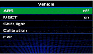
Advanced functions - ABS
- This function allows you to disable the ABS system that is normally active "On".
- Briefly pressing the MODE selector in the middle deactivates the function ("Off") and pressing it again reactivates it ("reactivate").
- Disabling is possible only when the vehicle is in "OFF ROAD" mode. If the riding mode is changed, ABS reactivates.
- To return to the "MENU", briefly press the MODE selector in the middle on "Exit".
CAUTION IT IS DISABLED ONLY TEMPORARILY, WHEN THE KEY IS INSERTED THE SYSTEM IS ALWAYS ACTIVE.
CAUTION DISABLING IS POSSIBLE ONLY WHEN THE VEHICLE IS IN "OFF ROAD" MODE. IF THE RIDING MODE IS CHANGED, ABS REACTIVATES.
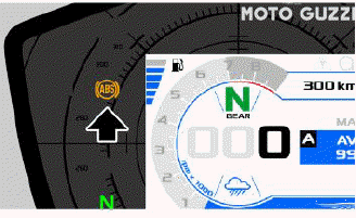
IF DISABLED, THE ABS INDICATOR LIGHT STAYS ON STEADY.
- Upon starting the vehicle, after the initial instrument panel check, the ABS warning light flashes until a speed of 5 kph (3.11 mph) is exceeded and then it switches off or continues to flash even after exceeding the speed of 5 kph (3.11 mph).
- If the ABS warning light continues flashing or is permanently on, a failure has been detected and the ABS has been automatically deactivated.
Characteristic
Distance between tone wheel and front sensor 0.1 - 3.17 mm (0.004 - 0.125 in) Distance between tone wheel and rear sensor 0.1 - 3.10 mm (0.004 - 0.122 in)
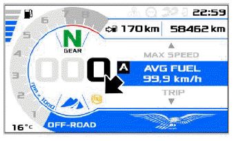
- In OFF ROAD mode, the ABS system deactivates automatically for the rear wheel.
CAUTION ONLY IN THIS MODE DOES THE ABS SYSTEM STAY ACTIVE EXCLUSIVELY FOR THE FRONT WHEEL AND THE DEDICATED SYMBOL APPEARS ON THE DISPLAY TO REMIND THE RIDER TO TAKE PARTICULAR CARE.
See also:
 Moto Guzzi V85 TT - Service manual > Modulator
REMOVAL Remove the engine from the vehicle PREPARING THE VEHICLE Connect the bleeder bottles to the front and rear calliper bleeder screws and open them. Press the front brake lever and the rear brake pedal as far as they will go and block them in position using the clamping devices. Close the front and rear calliper bleeder screws and remove the bleeder bottle Mark a reference on the pipes and on the ABS control unit to avoid inverting them when refitting Undo and remove the screw (1) Undo and remove the screw (2) Remove the support bracket (3) Disconnect the connector (4) Unscrew and remove the screws (5) Remove the ABS control unit (6)
 Ducati Scrambler
 Fantic Caballero 500
 Indian FTR 1200
 Moto Guzzi V85 TT
 Royal Enfield Bullet Trials Works Replica
 Triumph Scrambler 1200 XE
 Triumph Street Scrambler
 Yamaha XSR700
 Ducati Scrambler 800
 Moto Guzzi V85 TT
 Triumph Scrambler 1200 XC