 Triumph Scrambler 1200 XC - Service manual > Tracing Circuits
The following is a description of two types of common electrical failures, and some of the methods which may be used to find them.
Open Circuit
A break in an electrical circuit - current cannot flow. Usually caused by a break in a wire or cable or by a loose connection. Open circuits can often be intermittent, making diagnosis difficult.
Short Circuit
A 'short cut' in an electrical circuit - current bypasses the intended circuit, either to ground or to another, different circuit. Often caused by failure of the cable insulation due to chafing or trapping of the wire. There are two different types of short circuit - short to ground and short to battery Voltage.
A short to ground means that the current is going to ground before it reaches the component it is supposed to feed. These are often caused by chafing of the harness to the frame or wires trapped between a bolted component, and will often blow the fuse on that circuit.
A short to battery voltage (12 Volts) is caused by a live power supply wire contacting an adjacent cable. Note that it is also possible for a 5 Volt sensor reference voltage to short to an adjacent circuit, which can also cause electrical failures and DTCs (Diagnostic Trouble Code) to be stored.
When tracing a wire that is suspect, carefully check the circuit diagram before starting. Remember:
- a wire may diverge at a splice and go off to feed other circuits. If these circuits are working, check for wiring faults from the splice onwards.
- the circuit diagram is not an accurate guide to the actual location of the parts when fitted on the motorcycle. It is a schematic diagram of the circuits.
- particularly where engine management items are concerned, the circuit is only completed by the ECM. If the ECM is not connected, the circuit may register as open.
To Check Continuity:
CAUTION
Ensure the circuit being tested is switched off before measuring continuity.
Damage to the Digital Multi Meter (DMM) may result from testing a 'live' circuit with the meter set to resistance (Ω).
In the example below, the ground circuit continuity is being tested from the battery to the frame.
- Locate each end of the wire.
- Set the Digital Multi Meter (DMM) to resistance check Ohms.
- Probe each end of the wire.
- If there is continuity, the meter will usually bleep or register the resistance of the cable.
- A high resistance figure could indicate a dirty or corroded connection.
- If there is a break in the wire, the meter will not bleep or register a resistance.
- By probing the wire in various places, the position of a high resistance or break in the wire (open circuit) can be narrowed down until it is found.
To Measure Voltage:
In the example below, the circuit voltage is being measured at the bulb positive (+) terminal.
- Turn the circuit to be tested 'ON'.
- Set the Digital Multi Meter (DMM) to Voltage Check (V). Ensure the multi meter is set to DC Volts for direct current circuits (most circuits) or AC Volts for alternating current circuits (typically alternator output voltage tests).
- Set the range of the DMM to the range best suited to the voltage of the circuit being tested (typically 20 Volts for most DMMs). Refer to the DMM manufacturers instructions.
- Connect the black (ground) lead of the DMM to a reliable ground connection (usually the battery or frame ground).
- Locate the positive terminal of the wire or component to be tested.
- Connect the red (positive) lead of the DMM to the positive terminal.
- Read the voltage from meter.
Splices
Splices are probably the most common cause of wiring faults after connectors.
Splices are made where two or more wires come together and diverge in different directions, usually to feed a different circuit.
To locate a splice, it is necessary to peel back the insulation and examine the splice for its integrity. The most common fault is where one of the wires at the joint has come adrift usually causing the circuit it feeds or grounds to become 'dead'.
Switches
To check a switch, set the multimeter to resistance/continuity and probe the two pins that form a closed circuit when the switch is pushed. If the switch is working correctly, the resistance should register or the meter will bleep.
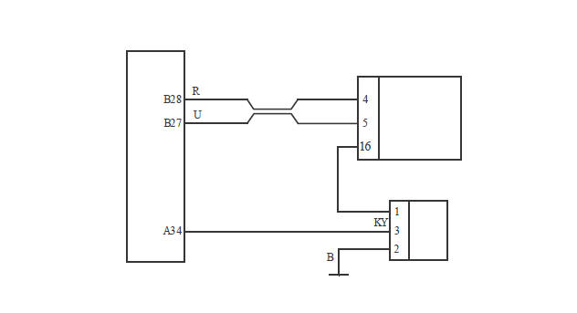
Relays
All relay cases have a circuit path engraved on them showing the circuit path across the electromagnet and the switch. Before making any checks, first note the pin designations, current paths, and whether or not there is a diode in either circuit path.
Make continuity checks across the electromagnet first, usually from pin 86 (positive) to pin 85 (negative). If a diode appears in the circuit use the diode check on the multimeter (Volts scale) in the direction of current flow. If there is no diode, use the resistance check facility. An open circuit or unusually high resistance value indicates a faulty relay.
To check the switch side, apply a 12 Volt supply between pins 86 and 85. With the supply connected, the relay should be heard to click and there should be continuity between pins 30 and 87. An open circuit indicates a faulty relay.
CAN (Controller Area Networking)
CAN (sometimes called CANbus) is a protocol for data communication between Electronic Control Modules (ECMs). Each ECM on the network is connected by a single pair of twisted wires (or bus) which are used for the transmission of vehicle sensor data. By using CAN, the overall number of system sensors, and the amount of cabling required to allow ECMs to communicate with each other is greatly reduced.
This saves cost, weight and space, and makes the system more reliable, as the physical number of wires and connections is reduced.
CAN works by each ECM sending out 'packets' of information (such as engine speed or fuel consumption information) on to the network bus (note that the network must be free of data before any ECM is allowed to transmit). This data is given a priority according to its importance (for example 'engine speed' may have a higher priority than 'low fuel level'), so that even if two ECMs send data at the same time, high priority information is always sent first. Lower priority data is then resent after the high priority data has been received by all ECMs on the network.
The receiving ECM confirms the data has been received correctly and that the data is valid, and this information is then used by the ECM as necessary. Specific data not required by an ECM will still be received and acknowledged as correct but then disregarded (for example if an ECM does not require 'clutch switch position' information, this data packet would be ignored).
This allows for a very high speed system of communication, which is also very reliable. Should one ECM fail or transmit corrupted or otherwise incorrect messages, none of the other ECMs on the network will be affected, and after a certain time that ECM will be prevented from transmitting further messages until the fault is rectified.
This stops the ECM from clogging the network with incorrect data and preventing other messages from getting through. The fault would then be reported by a DTC (Diagnostic Trouble Code).
Triumph currently uses CAN for communication between the following ECMs:
- Engine ECM
- Instruments
- ABS ECM
- Immobiliser or Chassis ECM
- Diagnostic connector
- Inertial Measurement Unit (if fitted)
- Audio system (if fitted)
- Electronic steering lock (if fitted)
- LED Headlights (if fitted).
LIN (Local Interconnect Network)
LIN (Local Interconnect Network) is a serial network protocol used for communication between components in vehicles. The bus is a single master/multiple slave bus that uses a single wire to transmit data.
By using LIN, the amount of cabling required to allow components to communicate with each other is greatly reduced. This saves cost, weight and space, and makes the system more reliable, as the physical number of wires and connections is reduced.
The instruments use some of this data internally and also broadcasts it on the CANbus (Controller Area Networking) for use on the motorcycle as necessary.
Information (such as headlight main beam) is being requested continuously by the Instruments, once a confirmation of the request is recognised the instruments will react accordingly.
- Instruments
- Switch housing (left hand side)
Example
- Pressing the headlight main beam button on the switch housing (left hand handlebar) confirms to the instruments that headlight main beam is required.
- The instruments confirm the data has been received correctly and that the data is valid.
- Once confirmed the headlight main beam is switched on.
Triumph currently uses LIN on certain models for communication between the instruments and the following components:
- Fog light button
- Heated seat
- Dip beam/Daytime running lights (DRL) switch (if equipped)
- Mode button
- Turn signal switch
- Joystick button
- Horn button
- High beam button
See also:
 Triumph Scrambler 1200 XC - Service manual > Electrical Testing
For any electrical system to work, electricity must be able to flow in a complete circuit from the power source (the battery) via the components and back to the battery. No circuit means no electrical flow. Once the power has left the positive side of the battery and run through the component it must then return to the battery on its negative side (this is called earth or ground). To save on wiring, connections and space, the negative side of the battery is connected directly to the frame or engine.
Triumph Scrambler 1200 XC - Service manual > Service Tools
Service Tools Special service tools have been developed to facilitate removal, dismantling and assembly of certain mechanical components in a practical manner without causing damage. Some operations in this Service Manual cannot be carried out without the aid of the relevant service tools. Where this is the case, the tools required will be described during the procedure.
 Ducati Scrambler
 Fantic Caballero 500
 Indian FTR 1200
 Moto Guzzi V85 TT
 Royal Enfield Bullet Trials Works Replica
 Triumph Scrambler 1200 XE
 Triumph Street Scrambler
 Yamaha XSR700
 Ducati Scrambler 800
 Moto Guzzi V85 TT
 Triumph Scrambler 1200 XC