 Triumph Scrambler 1200 XC - Service manual > Clutch Controls
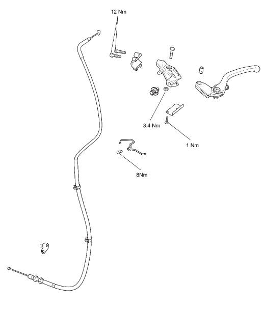
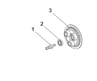
Exploded View - Clutch Controls
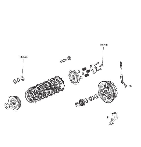
Exploded View - Clutch
Clutch Cable - Removal
WARNING
Before starting work, ensure the motorcycle is stabilised and adequately supported. This will help prevent it from falling and causing injury to the operator or damage to the motorcycle.
Perform the following operations:
- Seat - Removal
- Battery - Removal
- Fuel Tank - Removal
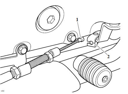
1. Loosen the cable lock nut and release the adjuster at the clutch cover end to give maximum play in the cable.
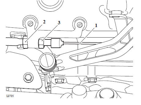
- Clutch cable
- Adjuster nut
- Lock nut
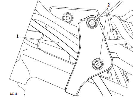
2. From the left hand side of the headstock, remove the cable retaining bracket and discard its fixings.
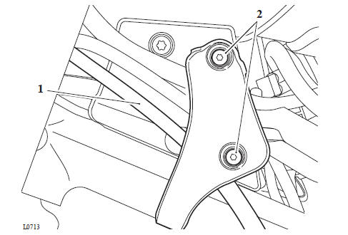
- Clutch cable
- Fixings
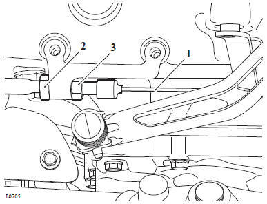
3. Detach the inner clutch cable from the boss on the clutch actuating arm.
- Clutch cable
- Boss
4. Detach the cable retaining guides from the frame down tube.
5. Align the cable adjuster and lever bracket slots.
6. Pull in the clutch lever and turn the inner cable adjuster anticlockwise through the lock nut, until the cable can be detached from the lever.
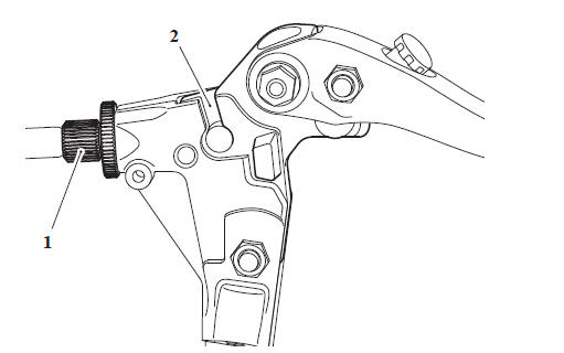
- Cable adjuster/ lever bracket slots
- Cable release point
Note
To ensure the same route can be followed on installation, tie a length of string to one end while pulling the cable through from the other. When installing the new cable, tie the string to one end of the cable and use it to guide the new cable into position.
7. Noting the cable routing and retaining guides, remove the cable from the motorcycle
Clutch Cable - Inspection
1. Check the inner cable for free movement through the outer cable.
2. Examine the inner cable for frayed strands.
3. Examine the two inner cable nipples for signs of looseness and damage.
Replace the cable if necessary.
Clutch Cable - Installation
WARNING
Before starting work, ensure the motorcycle is stabilised and adequately supported. This will help prevent it from falling and causing injury to the operator or damage to the motorcycle.
1. Ensure the steering is set to the straight ahead position.
2. Position the cable to the motorcycle following the same routing as noted during removal.
3. Attach the inner cable to the boss on the clutch actuating arm using a reversal of the removal process.
4. Refit the outer cable to the adjuster bracket at the clutch cover end.
- Clutch cable
- Adjuster nut
- Lock nut
5. Refit the cable retaining guides to the frame down tube.
6. Refit the cable retaining bracket to the headstock and using new fixings tighten to 3 Nm.
- Clutch cable
- Fixings
7. Set the lever adjuster to a point where an equal adjustment is possible in both directions.
8. Set the adjuster bracket at the clutch cover end to give a preliminary setting of 2 - 3 mm of free play as measured at the lever.
9. Operate the clutch lever several times and recheck the amount of free play present.
10. Tighten the clutch adjuster bracket lock nut at the clutch cover end to 3 Nm.
11. Set the final adjustment of the cable to give 1 - 2 mm of free play at the lever by turning the adjuster nut and lock nut at the lever end. Secure the setting with the knurled lock nut.
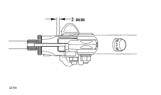
- Clutch lever
- Correct setting, 1 - 2 mm
Perform the following operations:
Perform the following operations:
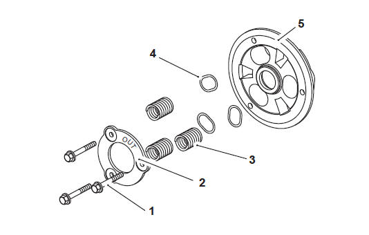
Clutch Lifter Arm - Removal
WARNING
Before starting work, ensure the motorcycle is stabilised and adequately supported. This will help prevent it from falling and causing injury to the operator or damage to the motorcycle.
Perform the following operations:
- Clutch Cover - Removal
Note
- If the clutch lifter arm is removed, the oil seal for the lifter arm in the clutch cover must be replaced.
- Note the orientation of the clutch lifter arm for installation.
- Note the position and orientation of the lifter arm spring for installation.
1. Remove the clutch lifter arm spring.
- Spring
2. Pull out the lifter arm from the clutch cover
- Clutch lifter arm plate
3. Using a suitable tool, carefully remove the oil seal in the clutch cover without damaging the clutch cover.
4. Check the condition of the needle roller bearings and the lifter arm for damage. If necessary renew the needle roller bearings and clutch lifter arm.
- Oil seal
- Clutch cover
- Needle roller bearings
Clutch Lifter Arm - Installation
WARNING
Before starting work, ensure the motorcycle is stabilised and adequately supported. This will help prevent it from falling and causing injury to the operator or damage to the motorcycle.
1. Press a new clutch lifter rod oil seal to the clutch cover, ensure the sealing lip is facing inwards.
2. Lubricate the seal lip with molybdenum disulphide grease and fit the clutch lifter arm into the clutch cover as noted for removal.
- Clutch lifter arm
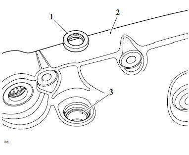
3. Before fitting the spring, ensure the lifter arm plate is positioned as shown in the following illustration.
- Clutch lifter arm plate
Note
The horizontal tang on the spring fits into the slot of the clutch lifter arm.
4. Fit the spring as noted for removal.
- Spring
5. Check the operation of the clutch lifter arm before installing the clutch cover.
Perform the following operations:
- Clutch Cover - Installation
Clutch - Removal
WARNING
Before starting work, ensure the motorcycle is stabilised and adequately supported. This will help prevent it from falling and causing injury to the operator or damage to the motorcycle.
Perform the following operations:
- Clutch Cover - Removal
Note
The spring seats will remain seated in the pressure plate during removal.
1. Release the three fixings, remove the stopper plate, springs and pressure plate.
- Fixings
- Stopper plate
- Springs
- Spring seats
- Pressure Plate
2. Remove the pull rod and bearing from the clutch pressure plate.
- Pull rod
- Bearing
- Clutch pressure plate
3. Remove the clutch plates, anti-judder seat washers and springs, noting the orientation of the each component as they are removed.
Note
- The two outermost and the inner friction plate are different to the remainder and must not be fitted in any other position.
- Refer to Friction Plate Inspection for details of clutch friction plate inspection.
4. Engage second gear and lock the inner and outer clutch drums together using T3880307 - Clutch Anti-rotation Jig as shown below.
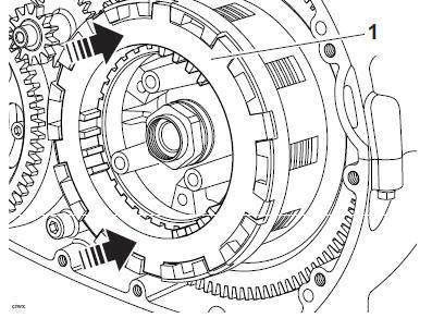
- T3880307 - Clutch Anti-rotation Jig
5. Release the clutch centre nut.
6. Remove the centre nut, Belleville washer, plain washer, clutch inner drum and thrust washer.
7. Discard both the Belleville washer and plain washer.
CAUTION
Do not remove the bearing sleeve from the shaft.
Removing the bearing sleeve will allow the oil pump drive chain to become dislodged.
If the oil pump drive chain becomes dislodged the oil pump will not operate causing severe engine damage.
8. Slide the bearing sleeve forward and backwards a maximum of 10 mm to allow the needle roller bearing to become dislodged.
9. Remove the needle roller bearing from the clutch outer drum.
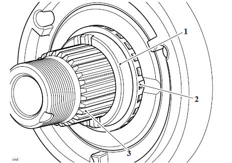
- Bearing sleeve
- Needle roller bearing
- Shaft
10. Slide the clutch outer drum away from the gearbox input shaft.
See also:
 Triumph Scrambler 1200 XC - Service manual > Friction Plate Inspection
Thickness Note If any friction plate thickness is outside the service limit, replace the friction plates as a set. 1. Measure the thickness of the friction plate. Clutch friction plate
 Ducati Scrambler
 Fantic Caballero 500
 Indian FTR 1200
 Moto Guzzi V85 TT
 Royal Enfield Bullet Trials Works Replica
 Triumph Scrambler 1200 XE
 Triumph Street Scrambler
 Yamaha XSR700
 Ducati Scrambler 800
 Moto Guzzi V85 TT
 Triumph Scrambler 1200 XC