 Triumph Scrambler 1200 XC - Service manual > Friction Plate Inspection
Thickness
Note
If any friction plate thickness is outside the service limit, replace the friction plates as a set.
1. Measure the thickness of the friction plate.
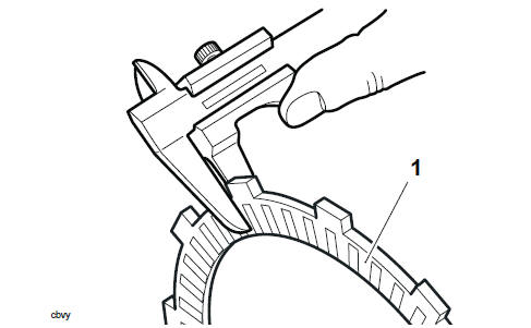
- Clutch friction plate
2. For the clutch friction plate thickness, refer to Clutch and Primary Drive.
Steel Plate Inspection
Bend/warp
Check all plates for bend and warp as follows:
1. Place the plate being checked on a clean surface plate and attempt to pass a feeler gauge of the maximum service limit thickness between the steel plate and surface plate. If the feeler gauge can be passed beneath the steel plate at any point, renew the plates as a set.
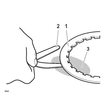
- Steel plate
- Feeler gauge
- Surface plate
2. For specifications refer toClutch and Primary Drive.
Clutch Pack - Height
Note
The clutch pack height is critical for a smooth operation of the transmission and must be measured prior to installation of new clutch plates.
When building a new clutch pack, its height must be correct. To achieve this, build the new clutch pack using the following:
- 2 x new outer friction plates
- 5 x new friction plates
- 1 x new inner friction plate
- 6 x steel plates, 2.0 mm thick
- 1 x outer steel plate, 2.0 mm thick
1. Arrange the new friction and new steel plates in a stack as shown below.
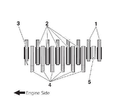
- Outer friction plates
- Friction plates
- Inner friction plate
- Steel plate, 2.0 mm thickness
- Outer steel plate, 2.0 mm thickness
2. Place the assembled clutch pack on a flat surface and measure its height as shown below.
- Clutch pack height
3. The clutch pack height for this clutch assembly is shown in the specification table see Clutch and Primary Drive.
4. If the clutch pack is too high, continue from step 5, omit step 6 then continue from step 7. If the clutch pack is too low, continue from step 6.
Note
- 1.6 mm and 2.3 mm steel plates are available, refer to the Parts Catalogue for part numbers.
- No more than one 1.6 mm thick steel plate is to be used in the clutch pack.
5. If the clutch pack height is too high, replace the 2.0 mm steel plate indicated below with a new 1.6 mm steel plate.
- 2.0 mm steel 1. plate to be replaced
Note
No more than one 2.3 mm thick steel plate is to be used in the clutch pack.
6. If the clutch pack height is too low, replace the 2.0 mm steel plate indicated below with a new 2.3 mm steel plate.
- 2.0 mm steel plate to be replaced
7. Recheck the clutch pack height as described previously.
Clutch - Installation
WARNING
Before starting work, ensure the motorcycle is stabilised and adequately supported. This will help prevent it from falling and causing injury to the operator or damage to the motorcycle.
CAUTION
Ensure the oil pump drive chain is engaged with the oil pump drive gears.
Running the engine without drive to the oil pump will stop oil supply to the engine.
Running the engine without oil pressure will cause severe engine damage.
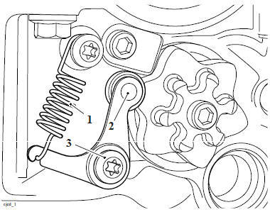
1. Visually check the oil pump drive chain is engaged with the drive gears.
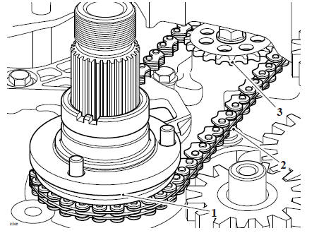
- Oil pump drive sprocket
- Oil pump drive chain
- Pump sprocket
2. Position the clutch outer drum assembly to the input shaft and align the oil pump sprocket drive pegs with the corresponding holes in the rear of the clutch outer drum.
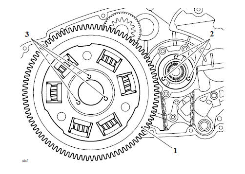
- Clutch outer drum (rear view)
- Oil pump sprocket drive pegs
- Clutch outer drum sprocket drive holes
3. While holding the clutch outer drum in position and ensuring correct engagement with the oil pump drive, refit the bearing.
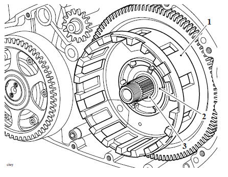
- Outer drum
- Bearing sleeve
- Needle roller bearing
Note
When the bearing and sleeve are correctly fitted, it will be a flush fit with the clutch drum face.
4. Fit the thrust washer to the shaft.
5. Fit the clutch inner drum.
6. Fit the flat washer, a new Belleville washer (OUT mark facing outwards), and a new centre nut.
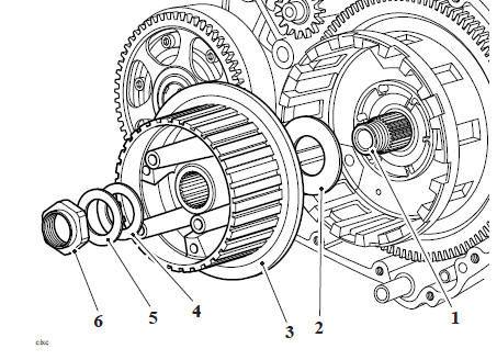
- Shaft
- Thrust washer
- Clutch inner drum
- Flat washer
- Belleville Washer OUT Mark
- Centre nut
7. Using T3880307 - Clutch Anti-rotation Jig, lock the inner and outer drums together. Depress the rear brake pedal to prevent the engine rotating, and tighten the centre nut to 98 Nm.
8. Remove T3880307 - Clutch Anti-rotation Jig.
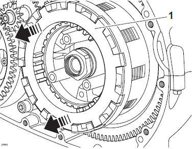
- T3880307 - Clutch Anti-rotation Jig
9. Disengage second gear and check for free rotation of the clutch inner drum.
10. Using a suitable pin punch, stake the nut to the shaft.
Note
Always refer to the Clutch Pack - Height prior to fitting new clutch plates to the motorcycle.
11. Coat all clutch friction plates in clean engine oil before fitting the friction plates, steel plates, anti-judder spring and anti-judder seat washer to the clutch basket in the same order and orientation as noted during removal.
Note
- The inner and the two outermost friction plates are different to the other friction plates. They must be fitted in their noted positions.
- The outer steel plate is different to the other plates. It must be fitted in its noted position.
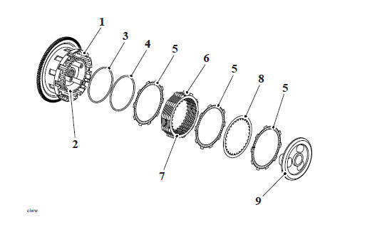
- Clutch outer drum
- Clutch inner drum
- Anti-judder seat washer
- Anti-judder spring
- Inner/outer friction plate
- Friction plates
- Steel plates
- Steel plate (outer)
- Pressure plate
12. Refit the clutch pull rod.
13. Fit the pressure plate. Ensure that the spring seats are fitted into the pressure plate as noted for removal.
- Note
- Note that the stopper plate has an OUT mark. This must face outwards when fitted.
- There are spring seats located in the pressure plate. Ensure the seats are in the pressure plate prior to fitting the springs.
14. Fit the springs and stopper plate, ensure that the OUT mark on the stopper plate is facing outwards. Secure with the fixings and tighten to 10 Nm.
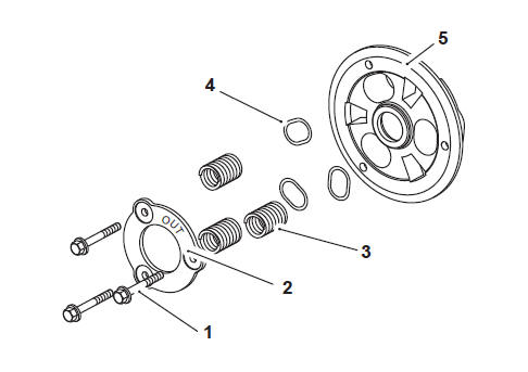
- Fixings
- Stopper plate
- Springs
- Spring seats
- Pressure plate
Perform the following operations:
- Clutch Cover - Installation
- Clutch Cable - Installation
- Battery - Installation
- Seat - Installation
See also:
 Triumph Scrambler 1200 XC - Service manual > Clutch Controls
Exploded View - Clutch Controls Exploded View - Clutch
 Ducati Scrambler
 Fantic Caballero 500
 Indian FTR 1200
 Moto Guzzi V85 TT
 Royal Enfield Bullet Trials Works Replica
 Triumph Scrambler 1200 XE
 Triumph Street Scrambler
 Yamaha XSR700
 Ducati Scrambler 800
 Moto Guzzi V85 TT
 Triumph Scrambler 1200 XC