 Triumph Scrambler 1200 XC - Service manual > Component Locations
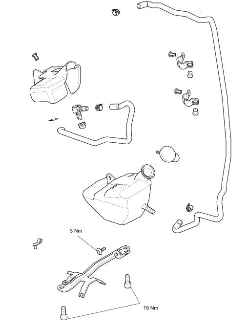
Evaporative Canister - under the airbox.
Purge Control Valve - (electronically controlled by the engine ECM) left hand side of the airbox behind the side panel.
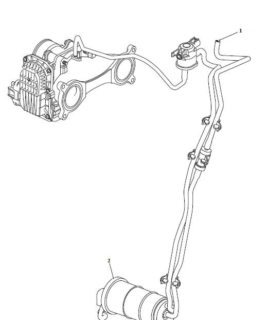
- Evaporative canister
- Purge valve
When the engine is stationary, any pressure increase in the fuel tank due to a rise in ambient temperature will cause the fuel vapour to pass down the breather pipe A to a carbon filled evaporative canister that stores the vapour.
Once in the canister, vapour cannot return to the fuel tank because the purge valve is closed.
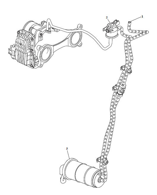
- Breather pipe A
- Evaporative canister
- Purge valve
When the engine is started, a vacuum is applied to the purge hose from the inlet manifold.
At certain times, the engine ECM opens the purge valve. The vacuum applied to the purge valve now begins to draw stored vapour from the carbon filled evaporative canister and returns it to the inlet manifold for burning in the engine.
In order to control the speed at which vapour is purged from the canister, the engine management system regularly shuttles the purge control valve between open and closed positions.
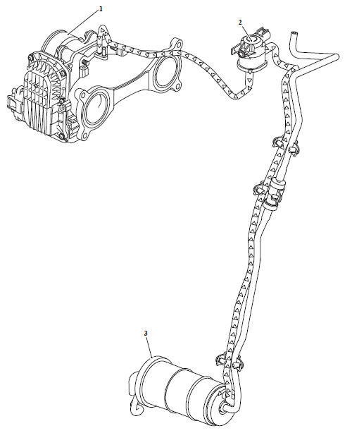
- Throttle bodies
- Purge valve
- Evaporative canister
WARNING
Before starting work, ensure the motorcycle is stabilised and adequately supported. This will help prevent it from falling and causing injury to the operator or damage to the motorcycle.
Perform the following operations:
- Sump Guard - Removal
Note
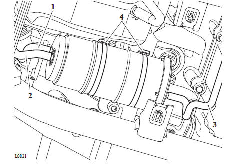
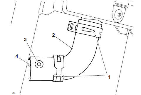
- Note the routing and locations of the hoses connected to the evaporative canister for installation.
- Not the orientation of the evaporative canister for installation.
1. Detach the hoses from the evaporative canister.
2. Cut and remove the two cable ties securing the evaporative emissions canister to the frame and remove the evaporative canister.
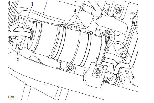
- Hose to purge valve
- Hose to fuel tank vent
- Hose evaporative cannister vent
- Cable ties
WARNING
Before starting work, ensure the motorcycle is stabilised and adequately supported. This will help prevent it from falling and causing injury to the operator or damage to the motorcycle.
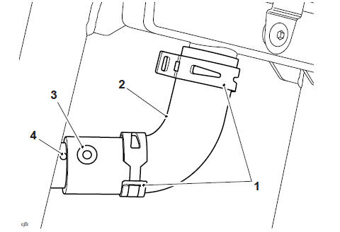
1. Connect the hoses to the evaporative canister as noted for removal.
2. Secure the evaporative canister to its mounting bracket with two cable ties as noted for removal.
- Hose to purge valve
- Hose to fuel tank vent
- Hose evaporative cannister vent
- Cable ties
Perform the following operations:
- Sump Guard - Installation
WARNING
Before starting work, ensure the motorcycle is stabilised and adequately supported. This will help prevent it from falling and causing injury to the operator or damage to the motorcycle.
Perform the following operations:
- Fuel Tank - Removal
Note
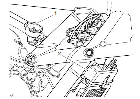
- The purge valve is located in front of the ignition coils.
- Note the position of the purge valve for installation.
- Note the routing of the purge valve hoses for installation.
1. Remove the fixing securing the purge control valve to its mounting bracket and manoeuvre it to left hand side of the frame.
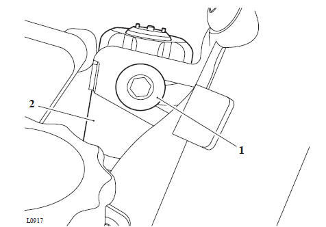
- Fixing
- Purge valve
2. Disconnect the electrical connector from the purge control valve.
3. Detach the two hoses and remove the purge control valve.
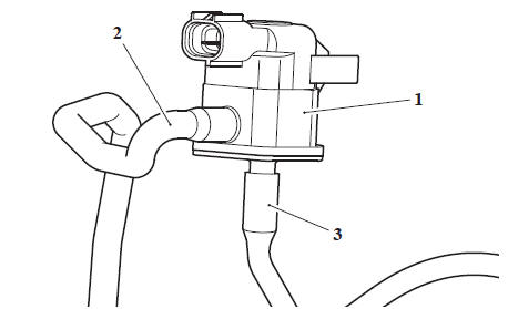
- Purge valve
- Hose (from evaporative cannister)
- Hose (to inlet manifold)
WARNING
Before starting work, ensure the motorcycle is stabilised and adequately supported. This will help prevent it from falling and causing injury to the operator or damage to the motorcycle.
1. Connect the hoses to the purge control valve as noted during removal.
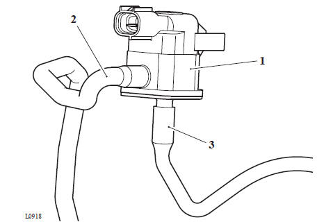
- Purge valve
- Hose (from evaporative cannister)
- Hose (to inlet manifold)
2. Connect the electrical connector to the purge control valve.
3. Position the purge control valve to its mounting bracket and tighten the fixing to 3 Nm.
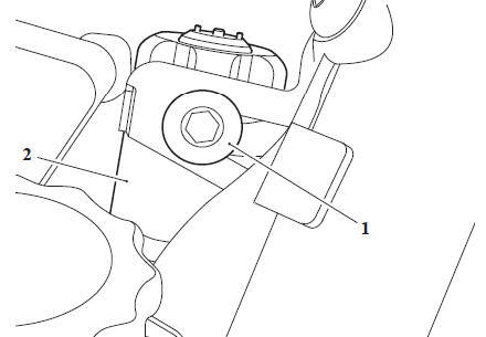
- Fixing
- Purge valve
Perform the following operations:
- Fuel Tank - Installation
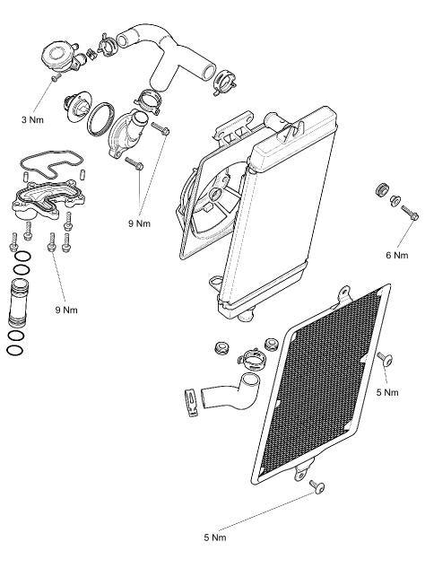
Check the radiator hoses for cracks or deterioration, and hose clamps for tightness in accordance with scheduled maintenance requirements.
Radiator
CAUTION
Using high pressure water, such as from a pressure-washer, can damage the radiator fins and impair the radiator's efficiency.
Do not obstruct or deflect airflow through the radiator by installing unauthorised accessories in front of the radiator or behind the cooling fan. Interference with the radiator airflow can lead to overheating and consequent engine damage.
1. Check the radiator for stone damage.
2. Check the radiator core for damage to fins or obstructions to air flow.
3. Clean off any obstructions with a stream of low-pressure water.
CAUTION
To avoid overheating and consequent engine damage, replace the radiator if the cores are blocked or if the fins are badly deformed or broken.
4. Rectify any damage.
Cooling Fan
WARNING
The cooling fan is switched on and off by the Engine Control Module in response to a signal received from the coolant temperature sensor. To prevent injury, never place loose clothing, fingers or hands near the cooling fan, until the engine is stopped. Loose clothing, fingers or the hands could become trapped during cooling fan operation and cause crushing injury to the fingers, hands or other parts of the anatomy.
The motorcycle is fitted with a thermostatically controlled electric fan situated behind the radiator. When the fan operates with the motorcycle stationary or at slow speed, cool air is drawn through the radiator from the front of the motorcycle.
1. Check that the cooling fan spins freely and without tight spots.
2. Check the cooling fan blades for signs of heat distortion.
3. Rectify as necessary.
A year-round, Hybrid Organic Acid Technology (known as Hybrid OAT or HOAT) coolant is installed in the cooling system when the motorcycle leaves the factory. It is coloured green, contains a 50% solution of ethylene glycol based antifreeze, and has a freezing point of -35ºC (-31ºF).
Always change the coolant at the intervals specified in the Scheduled Maintenance chart.
WARNING
The standard coolant mixture contains toxic chemicals that are harmful to the human body. Never swallow neat antifreeze or any of the coolant mixture.
CAUTION
The antifreeze incorporated in the coolant mixture contains a corrosion inhibitor that helps prevent damage to the cooling system and engine. Without this inhibitor, the coolant would 'attack' the metals and the resulting corrosion would cause blockages in the cooling system leading to engine overheating and damage.
Always use the antifreeze listed in the Specification section and never use a methanol based antifreeze as this does not contain the required corrosion inhibition properties.
Note
HD4X Hybrid OAT coolant, as supplied by Triumph, is premixed and does not need to be diluted prior to filling or topping up the cooling system.
CAUTION
If hard water is used in the cooling system, it will cause scale accumulation in the engine and radiator and considerably reduce the efficiency of the cooling system.
Reduced cooling system efficiency may cause the engine to overheat and suffer severe damage.
WARNING
Before starting work, ensure the motorcycle is stabilised and adequately supported. This will help prevent it from falling and causing injury to the operator or damage to the motorcycle.
WARNING
Do not remove the coolant pressure cap when the engine is hot. When the engine is hot, the coolant inside the radiator is hot and also under pressure. Contact with hot coolant will cause scalds and skin damage.
Note
- Prior to disassembly of the coolant hoses, note the orientation and position of the hose clamps to help ensure that they are returned to the same positions and orientation on assembly.
- Use T3880207 - Hose Clip Pliers for removal and installation of the hose clamps.
Perform the following operations:
- Seat - Removal
- Battery - Removal
- Fuel Tank - Removal
1. Remove the coolant pressure cap.
- Coolant pressure cap
2. Position a container below the engine and radiator to collect the displaced coolant.
3. Using T3880207 - Hose Clip Pliers, release the hose clamps then release the bottom hose from the radiator and allow the coolant to drain.
- Hose clamps
- Bottom hose
- Coolant hose alignment mark
- Hose alignment mark
4. Disconnect the bottom hose.
WARNING
Before starting work, ensure the motorcycle is stabilised and adequately supported. This will help prevent it from falling and causing injury to the operator or damage to the motorcycle.
WARNING
Do not remove the coolant pressure cap when the engine is hot. When the engine is hot, the coolant inside the radiator is hot and also under pressure. Contact with hot coolant will cause scalds and skin damage.
1. Refit the bottom hose. Ensure the hose is positioned to the alignment mark and the clamp is positioned as noted for removal.
- Hose clamps
- Bottom hose
- Coolant hose alignment mark
- Hose alignment mark
2. With the aid of an assistant, raise the rear wheel until the filler opening is above the radiator's upper coolant tank.
- Filler opening
- Radiator's upper coolant tank
3. Slowly add coolant mixture to the system, through the filler opening, until coolant escapes from the filler opening.
Note
If the system has filled correctly and fully, there should be coolant visible through the filler opening.
Note
During filling, squeezing the bottom hose with both hands will help to pump coolant around the system and remove trapped air.
4. Refit the coolant pressure cap.
5. Lower the motorcycle's rear wheel to the ground.
6. Refit the fuel tank (see Fuel Tank - Installation).
7. Reconnect the battery, positive (red) lead first and tighten the battery terminals to 4.5 Nm.
8. Start the motorcycle and allow the engine to idle. Briefly raise the engine speed several times to allow any air to be expelled from the system.
9. Stop the engine and allow it to cool.
10. With the aid of an assistant, raise the fuel tank to allow access to the coolant pressure cap.
11. Remove the coolant pressure cap.
12. If necessary, top up the system through the filler.
13. Refit the coolant pressure cap.
Perform the following operations:
- Fuel Tank - Installation
- Check the expansion tank level and top up if necessary (see Coolant Level Inspection).
- Seat - Installation
WARNING
Before starting work, ensure the motorcycle is stabilised and adequately supported. This will help prevent it from falling and causing injury to the operator or damage to the motorcycle.
Note
The oil pump and water pump are supplied as an assembly and cannot be separated. For additional information, refer to Oil Pump (see Oil and Water Pump - Removal for removal and Oil and Water Pump - Installation for installation).
1. Check the water pump face and shaft seals for signs of leakage. Renew the pump if leakage is evident.
WARNING
Before starting work, ensure the motorcycle is stabilised and adequately supported. This will help prevent it from falling and causing injury to the operator or damage to the motorcycle.
WARNING
Do not remove the coolant pressure cap when the engine is hot. When the engine is hot, the coolant inside the radiator is hot and also under pressure. Contact with hot coolant will cause scalds and skin damage.
1. Remove the fixing and position the coolant filler neck away from the immobiliser bracket.
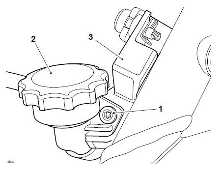
- Fixing
- Coolant pressure cap
- Immobiliser bracket
2. Remove the coolant filler cap.
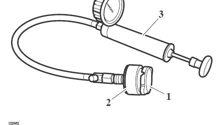
3. Select the T3880176 - Radiator Pressure Test (use with T3880147) bayonet type adapter and securely fasten to the coolant filler neck.
4. Carefully connect the hand pump (part of T3880147 - Radiator and Cap Tester Kit) to the T3880176 - Radiator Pressure Test (use with T3880147) ensuring an air tight seal is maintained.
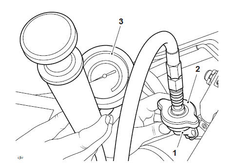
- Coolant filler neck
- T3880147 - Radiator and Cap Tester Kit
- Hand held pump (part of T3880147 - Radiator and Cap Tester Kit)
Note
Do not exceed 1.2 bar when carrying out a coolant pressure test.
5. Pressurise the cooling system to the operating pressure, using the hand pump, taking care not to exceed 1.2 bar.
6. Hold the pressure for a minimum of 10 minutes, whilst visually inspecting the external components of the coolant system for leaks.
Note
- If the engine oil is contaminated further exploratory investigation will be required.
- Engine oil with a hazy or milky appearance may indicate water emulsion.
- If the engine oil is contaminated rectify the cause of the problem and then renew the oil and filter.
7. Remove the engine oil filler cap and check for contamination of the engine oil caused by coolant escaping into the engine sump.
8. De-pressurise the coolant test kit using the pressure release valve.
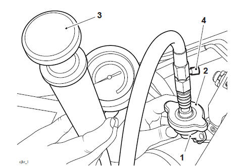
- Coolant filler neck
- Bayonet type connector
- Hand held pump
- Pressure release valve
9. Detach the T3880176 - Radiator Pressure Test (use with T3880147) bayonet type adapter from the coolant filler neck.
10. Refit the coolant filler neck and tighten 10. the fixing to 3 Nm.
Perform the following operations:
- Fill the coolant expansion tank to the maximum mark Coolant Level Adjustment
- Refit the coolant pressure cap
- Fuel Tank - Installation
- Battery - Installation
- Seat - Installation
Rear Suspension Units - Removal
WARNING
Before starting work, ensure the motorcycle is stabilised and adequately supported. This will help prevent it from falling and causing injury to the operator or damage to the motorcycle.
Do not remove the coolant pressure cap when the engine is hot. When the engine is hot, the coolant inside the radiator is hot and also under pressure. Contact with hot coolant will cause scalds and skin damage.
1. Allow the engine temperature to cool for at least 30 minutes.
2. Remove the coolant pressure cap.
3. Check the condition of the upper and lower seals of the coolant pressure cap.
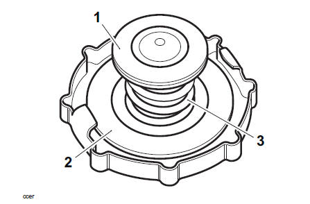
- Lower Seal
- Upper Seal
- Spring
Note
If there is any sign of damage or deterioration replace the cap.
4. Pressure test the cap and cooling system to the blow off pressure of 1.2 bar as described using T3880147 - Radiator and Cap Tester Kit.
Note
- It is recommended to carry out coolant pressure cap and cooling system pressure tests consecutively.
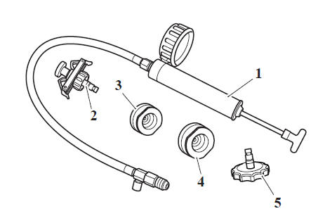
- Hand held pump
- Bayonet type connector
- Pressure cap test adapter 44 mm
- Pressure cap test adapter 46 mm
- Coolant cap type connector
5. Select the correct test adapter and securely fasten to the pressure cap.
6. Carefully connect the hand pump to the adapter ensuring an air tight seal is maintained.
- Pressure cap
- Test adapter
- Hand held pump
7. Pressure test the cap to it's 1.2 bar blow off pressure. If the coolant cap opens at a lower pressure, fails to open at the correct pressure or the seal leaks, replace the cap.
Perform the following operations:
- Refit the coolant pressure cap
- Fuel Tank - Installation
- Battery - Installation
- Seat - Installation
See also:
 Triumph Scrambler 1200 XC - Service manual > Exploded View - Rear Suspension Units
Exploded View - Swinging Arm WARNING Before starting work, ensure the motorcycle is stabilised and adequately supported. This will help prevent it from falling and causing injury to the operator or damage to the motorcycle.
 Ducati Scrambler
 Fantic Caballero 500
 Indian FTR 1200
 Moto Guzzi V85 TT
 Royal Enfield Bullet Trials Works Replica
 Triumph Scrambler 1200 XE
 Triumph Street Scrambler
 Yamaha XSR700
 Ducati Scrambler 800
 Moto Guzzi V85 TT
 Triumph Scrambler 1200 XC