 Triumph Scrambler 1200 XC - Service manual > Exploded View - Rear Suspension Units
Exploded View - Swinging Arm
WARNING
Before starting work, ensure the motorcycle is stabilised and adequately supported. This will help prevent it from falling and causing injury to the operator or damage to the motorcycle.
1. Check rubber mountings for cracks and wear, 1. replace if necessary.
2. Fit the rubber bushes and shouldered washers to the silencers rear mounting as noted for removal.
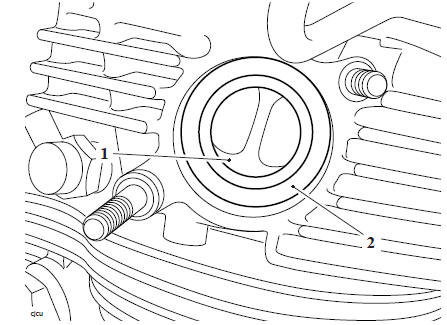
3. Fit new exhaust silencer gaskets to the catalytic converter, ensure they are positioned up to the collar.
- Exhaust gaskets
- Collar
- Catalytic converter
4. Fit the two rubber bushes and the shouldered washer to the lower mounting as noted for removal 5. Position the exhaust clamps onto the silencer.
6. Position the silencer assembly onto the catalytic converter.
7. Fit the lower mounting fixing, do not fully tighten at this stage.
- Fixing
- Shouldered washer
- Rubber bushes
8. Align the silencer upper mounting to the frame and fit the fixing but do not fully tighten at this stage.
- Fixing
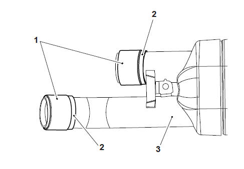
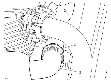
9. Position the exhaust gaskets into the silencer clamp area until flush with the end of the silencer clamp area.
- Clamp area
- Exhaust gasket
- Collar
10. Position the silencer clamps as noted for removal and tighten to 10 Nm.
- Upper silencer clamp
- Lower silencer clamp
- Catalytic converter
11. Tighten the silencer assembly upper fixing to 19 Nm.
12. Tighten the silencer assembly lower fixing to 19 Nm.
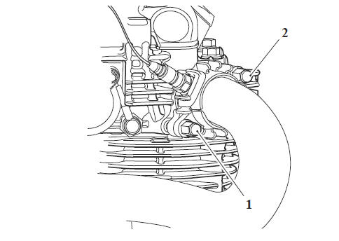
13. Position the inner and outer covers of the centre heat shield to the silencers, fit the fixings and tighten to 6 Nm.
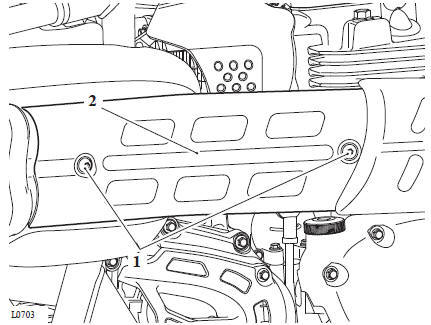
- Fixings
- Centre heat shield
14. Fit the two rubber grommets to the heat shield mounting bracket.
15. Fit the heat shield bracket to its locating lugs on the exhaust silencer. Fit and tighten the bracket rear fixing to 6 Nm.
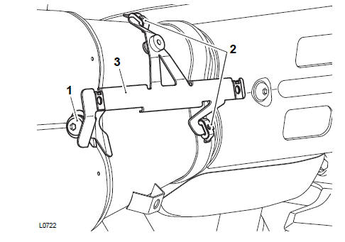
- Fixing
- Rubber grommets
- Heat shield bracket
16. Fit the rear heat shield and tighten its fixings to 6 Nm.
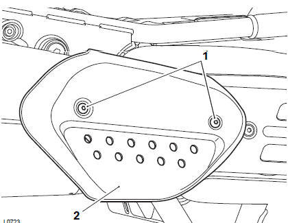
- Fixings
- Heat shield
17. Start the engine and check for exhaust gas leaks. Rectify if necessary.
Perform the following operations:
- Seat - Installation
WARNING
Before starting work, ensure the motorcycle is stabilised and adequately supported. This will help prevent it from falling and causing injury to the operator or damage to the motorcycle.
WARNING
If the engine has recently been running, the exhaust components may be hot to the touch. Contact with the hot components may cause damage to exposed skin.
To avoid skin damage, always allow the hot parts to cool before working on the exhaust system.
Note
- The right hand header pipe is part of the catalytic converter.
- Always note the position and orientation of exhaust clamps prior to releasing them, and return them to the noted position and orientation on assembly.
Perform the following operations:
- Seat - Removal
- Battery - Removal
- Fuel Tank - Removal
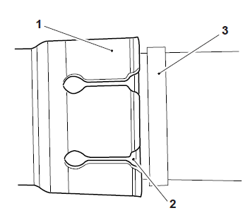
1. Loosen the clamp securing the left hand header pipe to thecatalytic converter.
- Exhaust clamp
- Left hand header pipe
- Catalytic converter
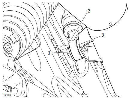
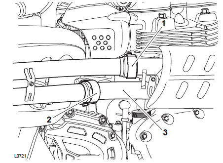
2. Release the fixing and detach the connector bracket from the right hand side of the headstock.
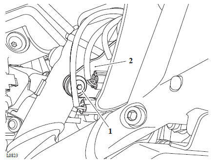
- Fixing
- Connector bracket
Note
- Note the routing of the oxygen sensor harness for installation.
- The oxygen sensor electrical connections must not be swapped between cylinders. If the connections are swapped over, engine malfunctions will occur.
- The right hand (Cylinder 2) oxygen sensor harness has a small section of red tape for identification.
- The oxygen sensors are NOT marked. Always ensure the right hand oxygen sensor harness is connected to the correct main harness connector, identified by the red tape.
3. Disconnect the left hand oxygen sensor from the main harness.
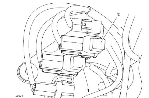
- Left hand oxygen sensor connector
- Right hand oxygen sensor connector
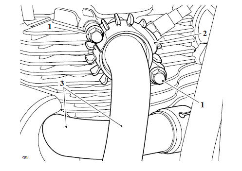
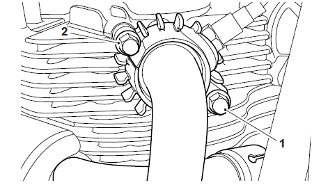
4. Remove the fixings and the finned clamps securing the exhaust header pipe to the cylinder head.
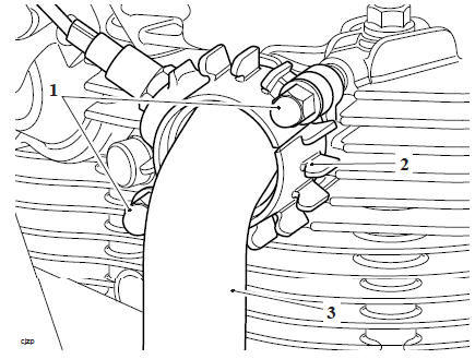
- Fixings
- Finned clamps
- Exhaust header pipe
5. Detach the exhaust header pipe from the catalytic converter, remove the exhaust header pipe. Remove and discard the gasket from the cylinder head ports.
6. Remove and discard the exhaust header pipe gasket from the catalytic converter.
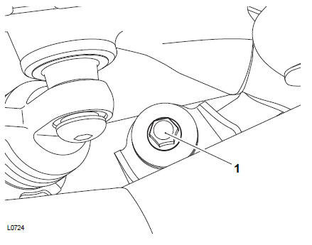
7. If necessary, remove the oxygen sensor.
WARNING
Before starting work, ensure the motorcycle is stabilised and adequately supported. This will help prevent it from falling and causing injury to the operator or damage to the motorcycle.
1. If removed, apply a thin smear of anti-seize compound to the threads of the oxygen sensor, install the oxygen sensor and tighten to 25 Nm.
2. Fit a new gasket to the header pipe and position the clamp over the joint.
Note
To retain the gaskets during assembly, apply a smear of grease or petroleum jelly to the gasket faces in the head.
3. Fit new gaskets to the cylinder head ports.
- Cylinder head port
- Gasket
4. Apply a proprietary high temperature grease to the header pipe studs on the cylinder head.
5. Locate the exhaust header pipe to the cylinder head, ensure the gasket does not become displaced during assembly. At the same time attach the header pipe to the catalytic converter.
6. Fit the fixings to the cylinder head studs and tighten in the sequence shown below.
Stage 1:
- Header pipe lower nut to 10 Nm
- Header pipe upper nut to 10 Nm
- Retighten the header pipe lower nut to 10 Nm.
- Header pipe lower nut
- Header pipe upper nut
Stage 2:
- Header pipe lower nut to 19 Nm
- Header pipe upper nut to 19 Nm
- Retighten the header pipe lower nut to 19 Nm.
Installation Continued
1.Position the exhaust header to catalytic converter clamp as noted for removal and tighten to 10 Nm.
2. Route the oxygen sensor harness as noted for removal and connect to the main harness as noted for removal.
3. Fit the connector bracket to the right hand side of the headstock and tighten its fixing to 3 Nm.
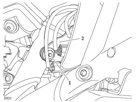
- Fixing
- Connector bracket
Perform the following operations:
- Fuel Tank - Installation
- Battery - Installation
- Seat - Installation
- Start the engine and check for exhaust gas leaks. Rectify if necessary
WARNING
Before starting work, ensure the motorcycle is stabilised and adequately supported. This will help prevent it from falling and causing injury to the operator or damage to the motorcycle.
If the engine has recently been running, the exhaust components may be hot to the touch. Contact with the hot components may cause damage to exposed skin.
To avoid skin damage, always allow the hot parts to cool before working on the exhaust system.
Note
Always note the position and orientation of exhaust clamps prior to releasing them, and return them to the noted position and orientation on assembly.
Perform the following operations:
- Seat - Removal
- Battery - Removal
- Exhaust Silencer - Removal
- Left Hand Header Pipe - Removal
- Fuel Tank - Removal
Note
- Note the routing of the oxygen sensor harness for installation.
- The oxygen sensor electrical connections must not be swapped between cylinders. If the connections are swapped over, engine malfunctions will occur.
- The right hand (Cylinder 2) oxygen sensor connector on the main harness has a red connector (main harness side).
- The oxygen sensors are NOT marked. Always ensure the right hand oxygen sensor harness is connected to the main harness connector with the red connector.
1. Disconnect the right hand oxygen sensor from the main harness.
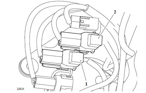
- Left hand oxygen sensor connector
- Right hand oxygen sensor connector
2. While supporting the catalytic converter, remove the fixings and the finned clamps securing the exhaust header pipe to the cylinder head. Remove the catalytic converter
- Fixings
- Finned clamps
- Catalytic conveter
3. If necessary, remove the oxygen sensor.
WARNING
Before starting work, ensure the motorcycle is stabilised and adequately supported. This will help prevent it from falling and causing injury to the operator or damage to the motorcycle.
1. If removed, apply a thin smear of anti-seize compound to the threads of the oxygen sensor, install the oxygen sensor and tighten to 25 Nm.
Note
To retain the gaskets during assembly, apply a smear of grease or petroleum jelly to the gasket faces in the head.
2. Fit a new gasket to the cylinder head right hand port
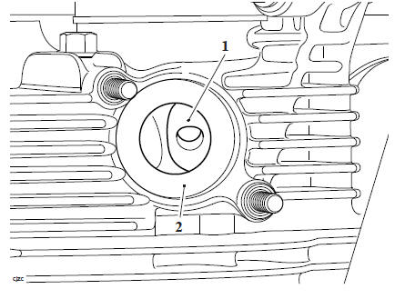
- Cylinder head port
- Gasket
3. Apply a proprietary high temperature grease to the header pipe studs on the cylinder head.
4. Locate the exhaust header pipe to the cylinder head, ensure the gasket does not become displaced during assembly.
5. Fit the fixings to the cylinder head studs and tighten in the sequence shown below.
Stage 1:
- Header pipe lower nut to 10 Nm
- Header pipe upper nut to 10 Nm
- Retighten the header pipe lower nut to 10 Nm
- Header pipe lower nut
- Header pipe upper nut
Stage 2:
- Header pipe lower nut to 19 Nm
- Header pipe upper nut to 19 Nm
- Retighten the header pipe lower nut to 19 Nm
1. Route the oxygen sensor harness as noted for removal and connect to the main harness as noted for removal.
2. Fit the connector bracket to the right hand side of the headstock and tighten its fixing to 3 Nm.
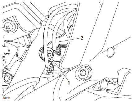
- Fixing
- Connector bracket
Perform the following operations:
- Left Hand Header Pipe - Installation
- Exhaust Silencer - Installation
- Fuel Tank - Installation
- Battery - Installation
- Seat - Installation
- Start the engine and check for exhaust gas leaks. Rectify if necessary.
Some models in certain markets are fitted with a system to control the evaporation of fuel vapour to the atmosphere.
A carbon filled evaporative canister absorbs vapour while the engine is not running.
When the engine is started, the vapour is returned to the engine and burned.
There are two distinct phases to the system's operation; engine off and engine running. These two conditions are explained overleaf.
See also:
 Triumph Scrambler 1200 XC - Service manual > Component Locations
Evaporative Canister - under the airbox. Purge Control Valve - (electronically controlled by the engine ECM) left hand side of the airbox behind the side panel. Evaporative canister Purge valve
 Ducati Scrambler
 Fantic Caballero 500
 Indian FTR 1200
 Moto Guzzi V85 TT
 Royal Enfield Bullet Trials Works Replica
 Triumph Scrambler 1200 XE
 Triumph Street Scrambler
 Yamaha XSR700
 Ducati Scrambler 800
 Moto Guzzi V85 TT
 Triumph Scrambler 1200 XC