 Triumph Scrambler 1200 XC - Service manual > Crankcase
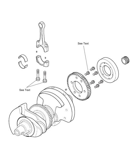
Exploded View - Crankshaft and Connecting Rod
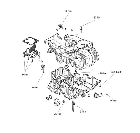
Exploded View - Crankcase
Crankcase - Disassembly
WARNING
Before starting work, ensure the motorcycle is stabilised and adequately supported. This will help prevent it from falling and causing injury to the operator or damage to the motorcycle.
Perform the following operations:
- Seat - Removal
- Battery - Removal
- Fuel Tank - Removal
- Engine - Removal
- Camshaft Cover - Removal
- Sump - Removal
- Alternator Rotor - Removal
Note
To allow correct fitment of T3880039 - Idler Gear Timing Pin the engine may require rotating up to seven times.
1. Align the timing holes in the crankcase and camshaft idler gear. Lock in position using T3880039 - Idler Gear Timing Pin.
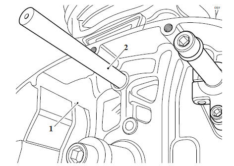
- Crankcase
- T3880039 - Idler Gear Timing Pin
2. Remove the oil and water pump (see Oil and Water Pump - Removal).
3. Release the fixing and remove the coolant drain tube, discard the fixing and the O-ring.
- Coolant drain tube
- Fixing
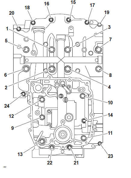
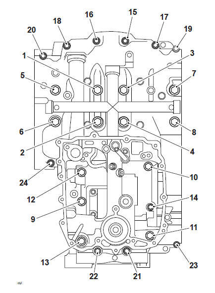
4. Release the lower crankcase fixings noting their positions in the sequence shown below.
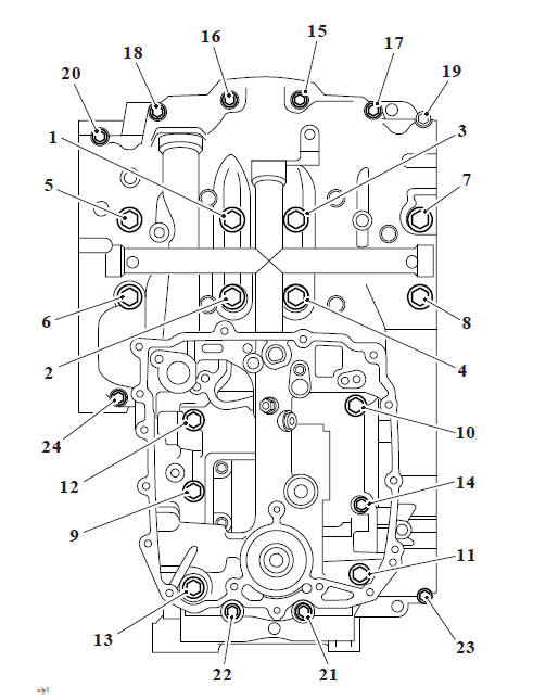
Crankcase Fixing Release Sequence
CAUTION
Do not use levers to separate the upper and lower sections of the crankcase as damage to the crankcases could result.
Note
Always check that all fixings have been released before attempting to separate the crankcases.
5. Separate the lower crankcase from the upper crankcase noting the position of the three location dowels.
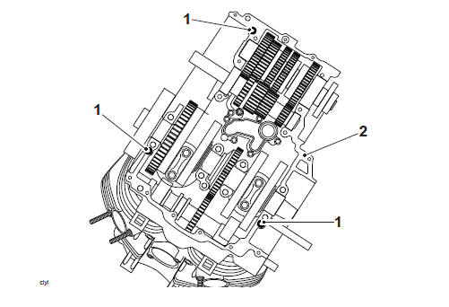
- Dowels
- Upper crankcase
Perform the following operations:
- Front Balancer Shaft - Removal
- Rear Balancer Shaft - Removal
- Crankshaft - Removal
- Selector Forks and Drum - Removal
- Coolant Manifold - Removal
- Breather Plate - Removal
Crankcase - Assembly
1. Use high flashpoint solvent to clean the crankcase mating faces. Wipe the surfaces clean with a lint-free cloth.
2. Position the transmission shafts and the selector drum in the 2. neutral position.
3. Ensure that the three dowels are located in position in the upper crankcase.
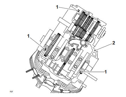
- Dowels
- Upper crankcase
4. Install and lubricate the crankshaft main bearing shells with clean engine oil (see page Crankshaft Main Bearing/Journal Checking, Measuring and Bearing Selection before proceeding).
5. Install and lubricate the front balancer shaft with clean engine oil (see Front Balancer Shaft - Installation).
6. Install and lubricate the rear balancer shaft with clean engine oil (see Rear Balancer Shaft - Installation).
7. Lubricate the crankshaft journals with clean engine oil.
8. Apply a 2 mm (+/-0.5 mm) bead of silicone sealant to the lower crankcase mating faces, (during manufacture, ThreeBond 1216E is used).

Sealer Areas
CAUTION
Do not use excessive amounts of sealer. The extra sealer may become dislodged and could block the oil passages in the crankcases, causing severe engine damage.
9. Position the lower crankcase to the upper crankcase. An assistant may be required to support the crankcase during alignment.
Note
- The rear balancer shaft will rotate one tooth when the upper and lower crankcase are joined.
10. To check that the balancer shaft is correctly timed to the crankshaft proceed as follows:
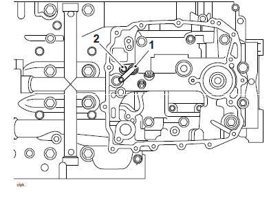
11. Check that the dot mark on the rear balancer shaft gear is aligned with the tab on the crankcase, as shown below.
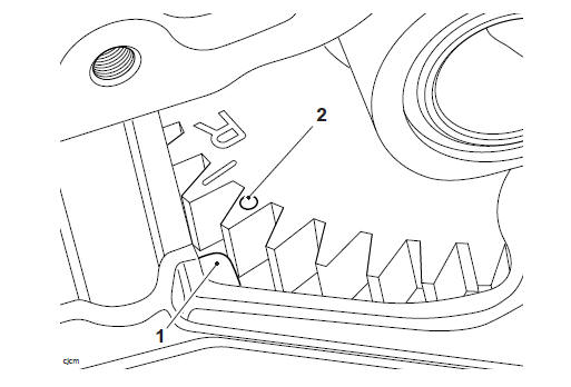
- Lower crankcase identification mark
- Rear balancer shaft dot mark
12. Locate the fixings into their respective positions in the lower crankcase as noted during removal and hand tighten.
13. Tighten the crankcase fixings as follows:
Note
The crankcase fixings are tightened in stages.
CAUTION
Failure to follow the correct tightening sequence may result in permanent crankcase damage.
Stage 1 - All Fixings
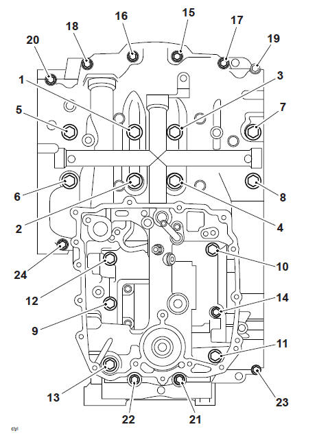
14. In the sequence shown below:
- Tighten all of the crankcase fixings to 10 Nm.
All Fixings Tightening Sequence
Stage 2
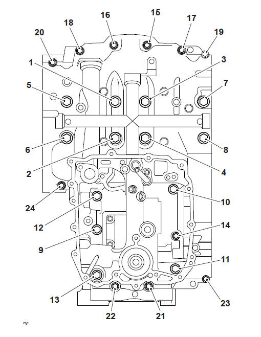
15. In the sequence shown below:
- Loosen fixings 1 to 8. through 140º, using T3880105 - Torque Angle Gauge or similar to measure the torque-angle.
Fixings 1 to 8 Loosening Sequence
Stage 3
16. In the sequence shown below:
- Tighten fixings 1 to 8 to 11 Nm.

Fixings 1 to 8 Tightening Sequence
17. In the sequence shown below:
- Tighten fixings 1 to 8 through a further 75º using T3880105 - Torque Angle Gauge or similar to measure the torque-angle.
Fixings 1 to 8 Tightening Sequence
Stage 4
18. In the sequence shown below:
- Tighten fixings 9 to 13 to 32 Nm.
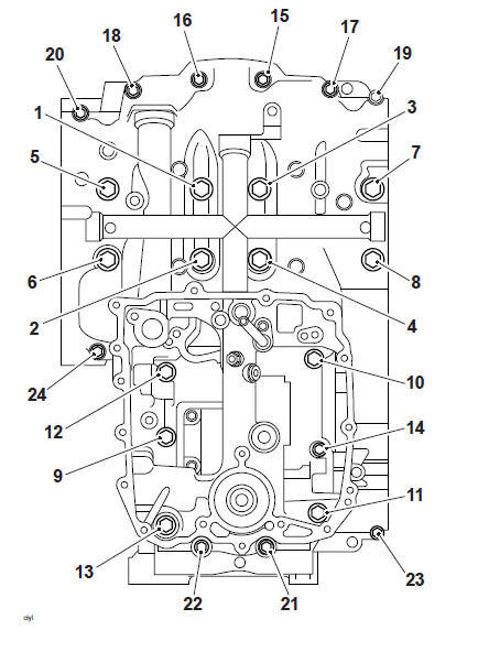
Fixings 9 to 13 Tightening Sequence
Stage 5
19. In the sequence shown below:
- Tighten fixings 14 to 24 to 12 Nm.
Fixings 14 to 24 Tightening Sequence
Note
- Prior to fitting an O-ring coat the surfaces with a commercially available petroleum jelly
20. Refit the breather drain tube, fit a new O-ring, tighten the new fixing to 9 Nm.
- Breather drain tube
- Fixing
Perform the following operations:
- Oil and Water Pump - Installation
- Sump - Installation
- Alternator Rotor - Installation
- Clutch - Installation
- Gear Position Sensor - Installation
- Engine - Installation
- Fuel Tank - Installation
- Battery - Installation
- Seat - Installation
Crankshaft - Removal
WARNING
Before starting work, ensure the motorcycle is stabilised and adequately supported. This will help prevent it from falling and causing injury to the operator or damage to the motorcycle.
Perform the following operations:
- Seat - Removal
- Battery - Removal
- Fuel Tank - Removal
- Engine - Removal
- Crankcase - Disassembly
- Connecting Rods - Removal
Note
Support the connecting rods during crankshaft removal to prevent damage to the rods, liners and upper crankcase.
1. Remove the crankshaft from the upper crankcase.
Crankshaft - Installation
CAUTION
Always check the main bearing journal clearance (see Crankshaft Main Bearing/Journal Checking, Measuring and Bearing Selection), before final assembly of the crankshaft. Failure to correctly select crankshaft bearings will result in severe engine damage.
1. Select and fit new main and big end bearing shells using the selection processes detailed in Crankshaft Main Bearing/Journal Checking, Measuring and Bearing Selection.
2. Lubricate all of the bearings with clean engine oil.
3. Ensure that the crankshaft is clean, and that the oil ways within the crankshaft are clean, free from blockages and debris.
CAUTION
The crankshaft to idler gear timing will be lost when the crankshaft is removed. Do not refit the crankshaft without first setting the crankshaft to idler gear timing.
Incorrect idler gear timing will result in incorrect camshaft timing. Rotating or attempting to start an engine with incorrectly adjusted camshaft timing will result in severe engine damage.
4. Install the crankshaft to the upper crankcase, ensuring the crankshaft drive gear is correctly timed to the balancer shafts and idler gear (see Front Balancer Shaft - Installation).
5. Align the connecting rod big ends to the crankshaft pins.
6. Fit, and in the correct sequence, tighten the big end caps. (see Connecting Rod - Installation).
7. Assemble the crankcases (see Crankcase - Assembly).
Perform the following operations:
- Barrels - Installation
- Cylinder Head - Installation
- Engine - Installation
- Fuel Tank - Installation
- Battery - Installation
- Seat - Installation
- Start the engine and ensure that the low oil pressure warning light goes out shortly after starting.
- Stop the engine and check the engine oil level. Adjust if necessary (see Engine Oil - Level Inspection).
See also:
 Triumph Scrambler 1200 XC - Service manual > Connecting Rods
Connecting Rods - Removal Perform the following operations: Fuel Tank - Installation Battery - Installation Seat - Installation
 Ducati Scrambler
 Fantic Caballero 500
 Indian FTR 1200
 Moto Guzzi V85 TT
 Royal Enfield Bullet Trials Works Replica
 Triumph Scrambler 1200 XE
 Triumph Street Scrambler
 Yamaha XSR700
 Ducati Scrambler 800
 Moto Guzzi V85 TT
 Triumph Scrambler 1200 XC