 Triumph Scrambler 1200 XC - Service manual > Connecting Rods
Connecting Rods - Removal
Perform the following operations:
- Fuel Tank - Installation
- Battery - Installation
- Seat - Installation
Note
The connecting rods and caps are etch-marked on one side to identify their correct orientation. However, the cylinder from which they are individually removed should also be identified, using a paint marker or similar.
- Engine - Removal
- Clutch - Removal
- Barrels - Removal
- Crankcase - Disassembly
- Remove and discard the connecting rod bolts.
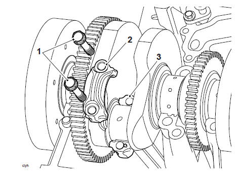
- Connecting rod bolts
- Connecting rod cap
- Connecting rod
1. Collect the connecting rod caps.
2. Collect the piston and connecting rod.
3. Label the assembly to identify the cylinder from which it was removed.
Connecting Rod - Installation
Note
The big end bolts are treated with an anti-rust solution, which must not be removed.
1. Clean the connecting rod with high flashpoint solvent.
2. Fit the piston and connecting rod assemblies to the crankshaft.
3. Select and fit the selected big end bearing shells to the connecting rods and big end caps (see Connecting Rod Big End Journal Checking, Measuring and Bearing Selection).
WARNING
Always renew the big end bolts. The bolts are torqued near to their yield point when first installed and are severely weakened if reused. Reusing the original bolts may cause bolt breakage resulting in engine damage, loss of motorcycle control and an accident.
The torque characteristics of the connecting rod bolts are sensitive to the rate at which they are tightened. If all the torque is applied in one action, the bolts will be stretched beyond their yield point. This may cause bolt breakage resulting in engine damage, loss of motorcycle control and an accident.
Note
- Prior to fitting the big end bolts lubricate the under head and thread areas of the bolts with undiluted molybdenum disulphide grease.
4. Fit new bolts to the connecting rods.
5. Tighten the bolts, in two stages as follows:
- Tighten to 15 Nm.
- Tighten through 210º using T3880105 - Torque Angle Gauge or similar.
T3880105 - Torque Angle Gauge
Perform the following operations:
- Crankcase - Assembly
- Barrels - Installation
- Engine - Installation
- Fuel Tank - Installation
- Battery - Installation
- Seat - Installation
Connecting Rod Big End Journal Checking, Measuring and Bearing Selection
Using selective bearings compensates for minor differences in crankshaft main bearing journal and crankcase dimensions. For further information on bearing part number to colour cross-references, refer to the electronic parts catalogue EPC.
1. Measure the bearing and crankshaft journal clearance as follows.
Note
Do not turn the connecting rod and crankshaft during the clearance measurement as this will damage the Plastigauge. The crankshaft journal clearances are measured using Plastigauge (Triumph part number 3880150- T0301).
2. Remove the bearing cap from the journal to be checked.
3. Wipe the exposed areas of the crankshaft journal, and the bearing face inside the cap.
4. Apply a thin smear of grease to the journal and a small quantity of silicone release agent to the bearing.
5. Trim a length of the Plastigauge to fit across the journal. Fit the strip to the journal using the grease to hold the Plastigauge in place.
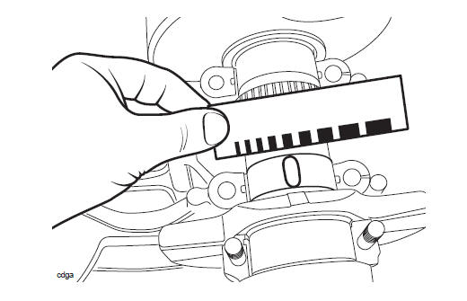
6. Release the fixings and remove the cap being measured. Using the gauge provided with the Plastigauge kit, measure the width of the compressed Plastigauge.
Note
The original fixings may be reused for bearing selection. Do not use new fixings as they may only be used once, even if the single use is related to bearing selection.
7. Lubricate the threads of the fixing and the face of the fixing with molybdenum disulphide grease. Refit the lower crankcase and tighten the original fixings (see Crankcase - Assembly).
8. Release the fixings and remove the cap being measured.
9. Using the Plastigauge kit, measure the width of the compressed Plastigauge.
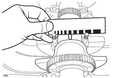
Checking the Big End Bearing/Crankshaft Journal Clearance
10. For specifications refer toCrankshaft.
11. If the clearance exceeds the service limit, measure the diameter of the crankshaft bearing journal.
Note
If any journal has worn beyond the service limit, the crankshaft must be replaced. Due to the advanced techniques used during manufacture, the crankshaft cannot be reground and no oversize bearings are available.
Connecting Rod Bearing Selection
Note
Minor differences in dimensions are compensated for by using selective bearings. For further information on bearing part number to colour crossreferences, refer to the EPC.
1. Select the correct bearing shell as follows: 2. Measure and record the diameter of each crankshaft bearing journal.
3. Measure and record each bearing bore diameter (bearings removed, journal caps fitted and all fixings fully torqued) (see Connecting Rod - Installation).
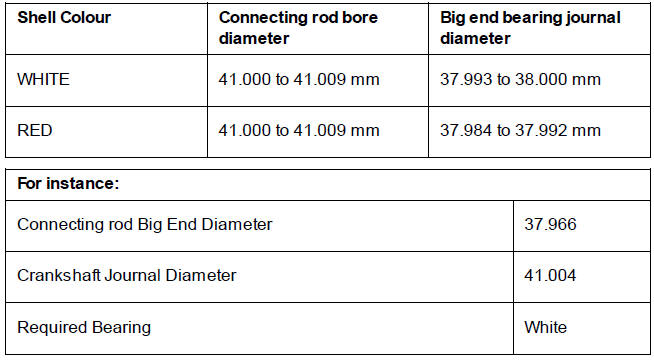
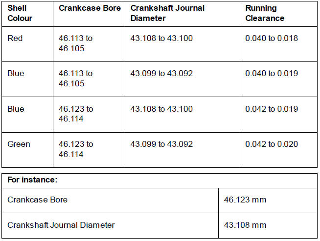
4. Select the correct bearings by matching the information found in the bearing selection chart.
5. Install the new bearings.
Big End Bearing Selection Chart
Note
- Repeat the measurements for all respective journals.
- It is normal for the bearings selected to differ from one journal to another.
- It is also normal for there to be two options of bearing shell colour. In such cases, pick the shell size that gives the greater running clearance.
WARNING
Always confirm, using the Plastigauge method, that the running clearance is correct before final assembly. Severe engine damage could result from incorrect clearance resulting in loss of motorcycle control and an accident.
Crankshaft Main Bearing/Journal Checking, Measuring and Bearing Selection
Using selective bearings compensates for minor differences in crankshaft main bearing journal and crankcase dimensions. For further information on bearing part number to colour cross-references, refer to the EPC.
1. Measure the bearing to crankshaft journal clearance as follows.
Note
Do not turn the connecting rods and crankshaft during the clearance measurement as this will damage the Plastigauge. The crankshaft journal clearances are measured using Plastigauge (Triumph part number 3880150- T0301).
2. Wipe the exposed areas of the crankshaft journals, and the bearing face inside the cap.
3. Apply a thin smear of grease to the journals and a small quantity of silicone release agent to the bearings.
4. Trim a length of the Plastigauge to fit across each journal. Fit the strip to the journal using the grease to hold the Plastigauge in position.
Note
The original fixings may be reused for bearing selection. Do not use new fixings as they may only be used once, even if the single use is related to bearing selection
5. Lubricate the threads and the face of the fixings with molybdenum disulphide grease. Refit the crankcase and tighten the original fixings (see Crankcase - Assembly).
6. Release the fixings and 6. remove the crankcase.
7. Using the Plastigauge kit, measure the width of the compressed Plastigauge.
Checking the Crankshaft Journal Clearance
8. For specifications refer toCrankshaft.
9. If the clearance exceeds the service limit, measure the diameter of the crankshaft bearing journal.
Note
- If any journal has worn beyond the service limit, the crankshaft must be replaced. Due to the techniques used during manufacture, the crankshaft cannot be reground and oversize bearings are not available.
Main Bearing Selection
Note
- Minor differences in dimensions are compensated for by using selective bearings. For further information on bearing part number to colour crossreferences, see the latest parts information.
1. Select the correct bearings as follows:
2. Measure and record the diameter of each crankshaft bearing journal.
3. Measure and record each bearing bore diameter in the crankcase (bearings removed, journal caps fitted and all fixings fully torqued).
4. Select and install the correct bearings by matching the information found in the main bearing selection chart.
5. Install the new bearings.
Main Bearing Selection Chart
WARNING
Always confirm, using the Plastigauge method, that the running clearance is correct before final assembly. Severe engine damage could result from incorrect clearance resulting in loss of motorcycle control and an accident.
Note
- Repeat the measurements for all respective journals.
- It is normal for the bearings selected to differ from one journal to another.
- It is also normal for there to be two options of bearing shell colour. In such cases, pick the shell size that gives the greater running clearance.
See also:
 Triumph Scrambler 1200 XC - Service manual > Crankcase
Exploded View - Crankshaft and Connecting Rod
Triumph Scrambler 1200 XC - Service manual > Coolant Manifold
Coolant Manifold - Removal WARNING Before starting work, ensure the motorcycle is stabilised and adequately supported. This will help prevent it from falling and causing injury to the operator or damage to the motorcycle.
 Ducati Scrambler
 Fantic Caballero 500
 Indian FTR 1200
 Moto Guzzi V85 TT
 Royal Enfield Bullet Trials Works Replica
 Triumph Scrambler 1200 XE
 Triumph Street Scrambler
 Yamaha XSR700
 Ducati Scrambler 800
 Moto Guzzi V85 TT
 Triumph Scrambler 1200 XC