 Triumph Scrambler 1200 XC - Service manual > Electrical Connectors
Before beginning any diagnosis, the following connector related information should be noted:
Note
- A major cause of hidden electrical faults can be traced to faulty electrical connectors. For example:
- Dirty/corroded terminals
- Damp terminals
For example, the engine electronic control module (engine ECM) relies on the supply of accurate information to enable it to plan the correct fuelling and ignition timing. One dirty terminal will cause an excessive voltage drop resulting in an incorrect signal to the engine ECM.
If, when carrying out fault diagnosis, a fault appears to clear by simply disconnecting and reconnecting an electrical plug, examine each disconnected plug for the following.
When Disconnecting a Connector:
- Check for a security device that must be released before the connector can be separated, e.g. barb, hook and eye etc.
When Inspecting a Connector:
- Check that the individual pins have not been bent
- Check for dampness/dirt/corrosion
- Check cables for security
- Check cable pin joints for damage.
When Connecting a Connector:
- Ensure there is no dirt around the connector/seal
- Push together squarely to ensure terminals are not bent or incorrectly located
- Push the two halves together positively.
Disconnection of the Engine ECM Connectors
CAUTION
When disconnecting a connector, never pull directly on the wires as this may result in cable and connector damage.
CAUTION
Never disconnect an ECM when the ignition switch is in the ON position as this may cause multiple fault codes to be logged in the ECM memory.
Always disconnect an ECM after disconnecting the battery negative (black) lead first.
1. Turn the ignition to the OFF position and wait at least 1 minute for the engine ECM to complete its power down sequence.
2. Detach the engine ECM from its bracket and the frame (see Engine Electronic Control Module (ECM) - Removal).
Note
Two different sized connectors are used in the engine ECM, which ensures correct connection is always made. The connectors are coloured black and correspond with identical connectors on the main harness.
1. Press down on the locking device and gently pull back on the connector to release it from the engine ECM.
- Locking device
- Locking lever
Reconnection of the engine ECM Connectors
CAUTION
Damage to the connector pins may result if an attempt to fit the connectors incorrectly is made.
1. Fit the connector into its socket. When the locking lever starts to move, stop pushing the connector and use the locking lever to fully insert the connector home and lock it.
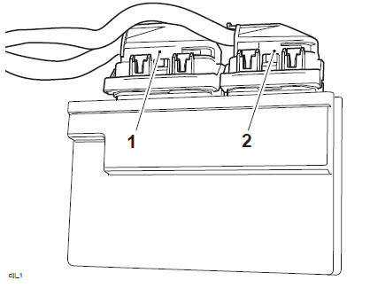
- Connector B (large)
- Connector A (small)
1. Refit the engine ECM and its bracket to the frame under the seat (see Engine Electronic Control Module (ECM) - Installation).
System Diagnostics
The engine management system has an on-board diagnostics feature which allows service technicians to retrieve stored data from the ECM using Triumph diagnostic software. Full details of the Triumph diagnostic software operation and how to interpret the results are given in the Triumph Diagnostic Tool User Guide.
The software is connected, via an interface cable, to the motorcycle using a dedicated diagnostic plug situated behind the left hand side panel. By using a dedicated plug, no electrical connectors associated with the system are disturbed, reducing potential connector damage.
The software allows the user to retrieve data associated with the system sensors and actuators, test various component functions, read build data and make minor adjustments to the set-up of the system. The data and tests available are described on the following pages.
On-board Fault Detection System
The on-board diagnostic system has two stages to fault detection. When a fault is detected, the DSM (Diagnostic Status Manager) raises a flag to indicate that a fault is present and increments a counter. The counter checks the number of instances that the fault is noted. For example, if there is a fault in the crankshaft position sensor, the counter will increment its count each time the crankshaft turns through 360º, provided the fault is still present.
When the count begins, the fault is detected but not confirmed. If the fault continues to be detected and the count reaches a predetermined threshold, the fault becomes confirmed. If the fault is an emissions related fault or a serious malfunction affecting engine performance, a DTC (Diagnostic Trouble Code) and freeze-frame data will be logged in the ECM's memory and the MIL (Malfunction Indicator Lamp) on the motorcycle instrument panel is illuminated. Once a fault is confirmed, the number of warm-up cycles made by the engine is counted. If the fault clears, the warm-up cycle counter will extinguish the MIL (Malfunction Indicator Lamp) at a predetermined count, and erase the DTC and freeze-frame data from the ECM memory at another (higher) count.
A single warm-up cycle is deemed to have taken place when the following criteria have been met:
- The coolant temperature must be raised to 72ºC or more.
- The coolant temperature must have risen by 23ºC or more from its start temperature, when 72ºC is reached.
- A controlled power down sequence must take place.
Note
- When a fault has been rectified, the MIL will remain illuminated until sufficient non-fault warm-up cycles have taken place to turn it off. The MIL will be immediately extinguished if, after first rectifying the fault, the DTC (diagnostic trouble code) that caused the MIL illumination is erased from the ECM memory using the Triumph diagnostic software.
- In some cases, when a fault is detected, the engine management system will revert to a limp-home mode. In this mode, the engine will still function though the performance and fuel economy may be marginally affected. In some cases, the rider may not notice any appreciable difference from normal operation.
Serv ice Symbol/General Warning Symbol
 The service symbol will
illuminate for five seconds after the motorcycle start up
sequence as a reminder that a service is due in approximately 60 miles (100 km).
The service symbol will
illuminate for five seconds after the motorcycle start up
sequence as a reminder that a service is due in approximately 60 miles (100 km).
The service symbol will illuminate permanently when the mileage is reached, it will remain permanently illuminated until the service interval is reset using the Triumph Diagnostic tool.
 The general warning symbol will
flash if an ABS or engine management fault has
occurred and the ABS and/or MIL warning lights are illuminated. Rectify the
fault and
clear the diagnostic trouble codes using the Triumph Diagnostic tool.
The general warning symbol will
flash if an ABS or engine management fault has
occurred and the ABS and/or MIL warning lights are illuminated. Rectify the
fault and
clear the diagnostic trouble codes using the Triumph Diagnostic tool.
ECM Connector Pin Numbering
The above illustration shows the pin numbering system used in the engine management circuit diagram.
The smaller connector's pins are prefixed A and the larger connector pins B. As viewed on the mating face with the ECM (as per the illustration), pins are numbered from right to left with number one in the top right corner.
System Diagnostic Tool Connection
Diagnostic Tool Connection
- To connect the Triumph diagnostic interface to the motorcycle, remove the left hand side panel (see Side Panels) and release the diagnostic connector from its locating tang.
- Diagnostic connector
2. Plug the Triumph diagnostic interface directly into the diagnostic connector.
T3880057 - Triumph Diagnostic Interface
3. When the diagnostic session is completed, disconnect the Triumph diagnostic interface.
4. Refit the diagnostic connector to its locating tang and refit the left hand side panel (see Side Panels).
Triumph Diagnostic Software
Described on the following pages is the range of information which can be retrieved from the ECM's memory and the adjustments which can be performed using the Triumph diagnostic software.
The tables indicate which tests are performed by the on-board system and what information can be retrieved by the Triumph diagnostic software.
Note
- Full details of how to operate the software and how to interpret the data can be found in the Triumph Diagnostic Tool User Guide.
Build Data
The Build Data screen will display the following information:
- Motorcycle model
- Vehicle Identification Number (VIN)
- ECM type
- ECM ID
- ECM serial number
- Calibration number
- Date of last calibration download
- Total calibration downloads since manufacture
- The lock status of the ECM (ECM Locked, Unlocked or Not Applicable).
Current Data
The data available under Current Data is:
Sensor Data
When using this function it is possible to check the status of various sensors and actuators.
The data sets are divided into eight groups - Sensor Voltages, Sensor Readings, Injector Data, Ignition Data, Idle Speed and Throttle Data, Inputs, Outputs and Adaption Status. Each of these screens is described on the following pages.
Sensor Voltages
The data available under Sensor Voltages is:
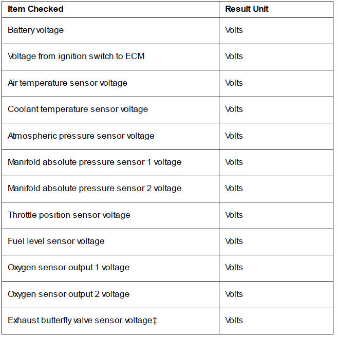
 Applies to models fitted with
an exhaust butterfly valve only. All other models will
show Not Applicable in this field.
Applies to models fitted with
an exhaust butterfly valve only. All other models will
show Not Applicable in this field.
Sensor Readings
The data available under Sensor Readings is:
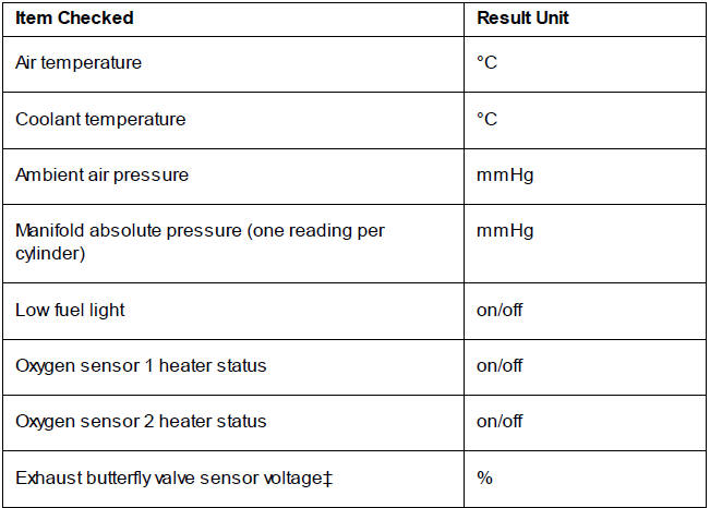
 Applies to models fitted with
an exhaust butterfly valve only. All other models will
show Not Applicable in this field.
Applies to models fitted with
an exhaust butterfly valve only. All other models will
show Not Applicable in this field.
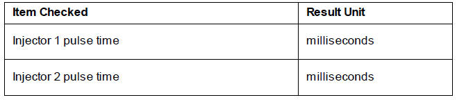
Inj ector Data
The data available under Injector Data is:
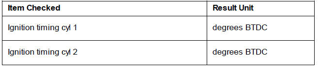
Ignition Data
The data available under Ignition Data is:
Idle Speed and Throttle Data
The data available under Idle Speed and Throttle Data is:
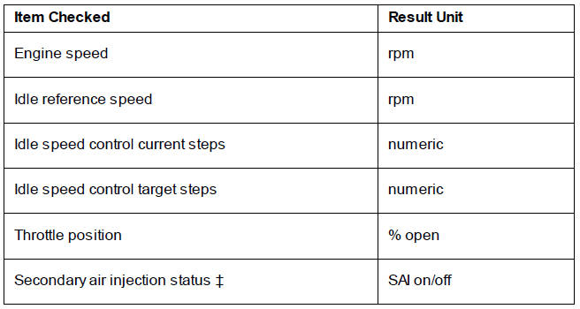
 Applies to models fitted with
secondary air injection only. All other models will show
Not Applicable in this field.
Applies to models fitted with
secondary air injection only. All other models will show
Not Applicable in this field.
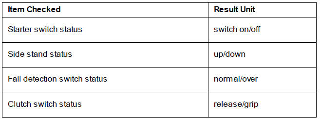
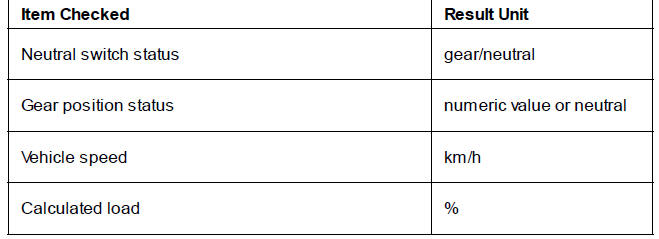
Inputs
The data available under Inputs is:
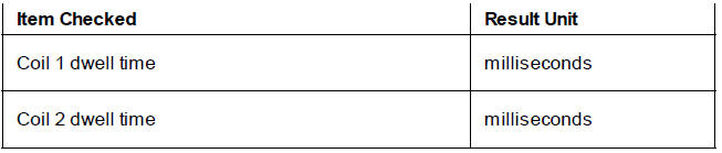
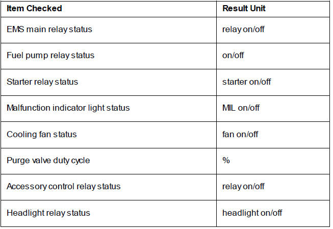
Outputs
The data available under Outputs is:
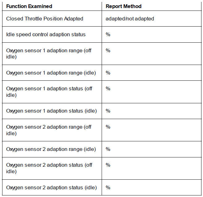
Adaption Status
Because the fuel system is adaptive, the engine management system is able to automatically adjust to new working conditions, such as changes in altitude, component wear, air leaks etc. This screen displays information on the adaption status of the vehicle which will show if it has adapted or not.
Function Tests
The system allows the diagnostic software to perform a series of function tests on various actuators in the engine management system. In some cases it is necessary to make a visual observation of a component and in others, if faults are present, DTCs will be logged.
The Function Tests available are:
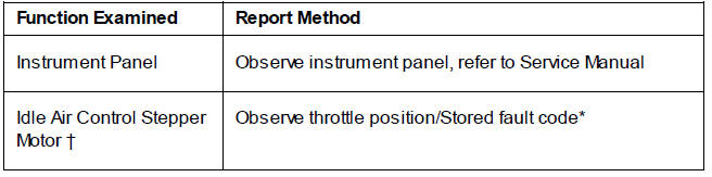
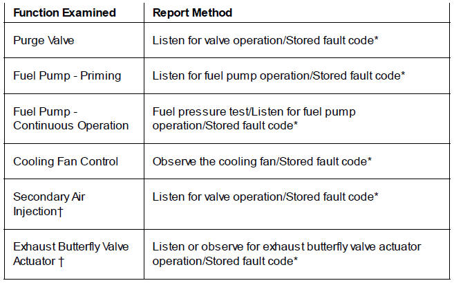
* If a fault is detected.
 Test will only be displayed if
the component is fitted.
Test will only be displayed if
the component is fitted.
Adj ust Calibration
Using the Triumph diagnostic software, it is possible to:
- reset the adaptions
- balance the throttle bodies.
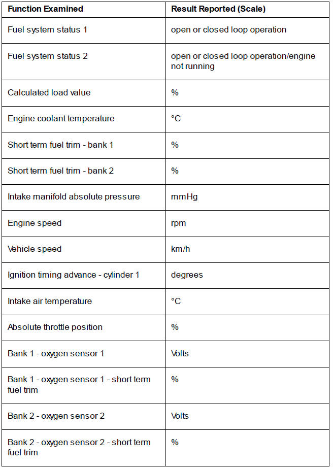
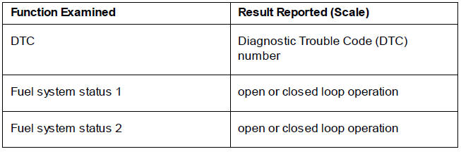
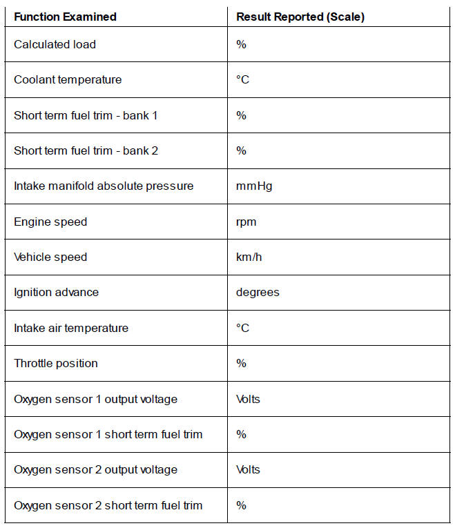
Freeze-Frame Data
Freeze-frame data is stored at the time a DTC is recorded (confirmed) by the ECM. If multiple DTCs are recorded, the freeze-frame data which is stored will relate to the first recorded DTC only.
By calling up freeze-frame data associated with the first recorded DTC, the technician can check the engine condition at the time the fault occurred. The data available is:
See also:
 Triumph Scrambler 1200 XC - Service manual > Gear Position Sensor
This model is fitted with a hall effect gear position sensor that provides a constant voltage output ranging from 0.5 to 4.5 Volts. The output voltage is used to determine which gear is currently engaged.
 Ducati Scrambler
 Fantic Caballero 500
 Indian FTR 1200
 Moto Guzzi V85 TT
 Royal Enfield Bullet Trials Works Replica
 Triumph Scrambler 1200 XE
 Triumph Street Scrambler
 Yamaha XSR700
 Ducati Scrambler 800
 Moto Guzzi V85 TT
 Triumph Scrambler 1200 XC