 Triumph Scrambler 1200 XC - Service manual > Gear Position Sensor
This model is fitted with a hall effect gear position sensor that provides a constant voltage output ranging from 0.5 to 4.5 Volts. The output voltage is used to determine which gear is currently engaged.
Voltage Characteristics
The gear position is determined by the following voltage ranges:
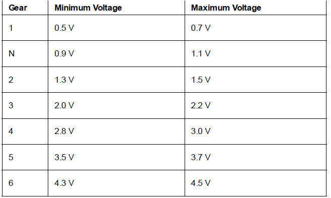
The sensor voltage can be read using the Triumph diagnostic tool.
Further Diagnostics
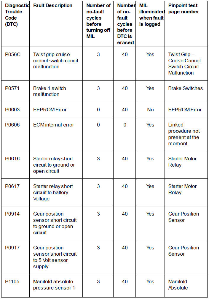
Refer to Gear Position Sensor for details of pinpoint tests relating to diagnostic trouble codes P0914 and P0917.
Neutral Position Adaption
The motorcycle is delivered from the factory with the neutral position fully adapted.
The neutral position adaption must be reset and re-adapted under the following conditions:
- If a gear position sensor malfunction occurs (DTC P0914 and P0917, see Gear Position Sensor).
- The sensor has been removed or disconnected for any reason.
Refer to Neutral Position Adaption
Neutral Position Adaption
The neutral position adaption is required to allow for manufacturing tolerances of the gearbox and gear position sensor. The motorcycle is delivered from the factory with the neutral position fully adapted.
The neutral position adaption must be reset and re-adapted under the following conditions:
- If a gear position sensor malfunction occurs (DTC P0914 and P0917), see Gear Position Sensor.
- The gear position sensor has been removed or disconnected.
Adaption Reset
To reset the neutral position adaption:
1. Connect the Triumph diagnostic tool and turn 1. the ignition ON.
2. Select ENGINE DIAGNOSTICS.
3. Check and erase any stored DTCs.
4. Select ADJUST TUNE then select Gear Position/Neutral Position Adaption Reset.
5. Click Start.
6. The software will confirm that the adaption has been successfully reset.
Re-Adaption
WARNING
Never start the engine or run the engine in a confined area. Exhaust fumes are poisonous and can cause loss of consciousness and death within a short period of time. Always operate your motorcycle in the open-air or in an area with adequate ventilation.
To re-adapt the neutral position:
1. Ensure the transmission is in neutral.
2. Start the engine.
Note
- For successful and accurate adaption, The engine must be at normal idle speed and the gear change pedal must be in its normal rested position.
- During adaption, do not raise the engine speed and do not touch or move the gear change pedal.
3. The neutral position will adapt shortly after engine start provided the above conditions are met.
4. The adaption status can be confirmed by selecting GEAR POSITION ADAPTION STATUS on the Triumph diagnostic tool.
Cruise Control Switch Check
The cruise control switch check is required after certain DTCs or defects have been repaired which relate to the ride by wire system or cruise control system, or after the adaptions have been reset. The switch check requires the user to operate the switches in order, following the instructions on screen.
The following switches will be checked:
- Front brake switch
- Rear brake switch
- Clutch lever switch
- Twist grip cruise cancel switch (operated by holding the twist grip in the fully closed position)
- Cruise control ON/OFF switch
A malfunction of any switch will not necessarily cause a DTC to be stored and may prevent the cruise control from operating correctly.
Note
If the cruise control switch check is not carried out, the green cruise control warning light will illuminate when the ignition is turned to the ON position but the cruise function will be disabled.
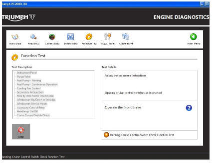
Cruise Control Sw itch Check Function
If the engine is running you will be prompted to turn it off before the test will start.
If the cruise control is turned on, you will be prompted to turn it off before the test will start.
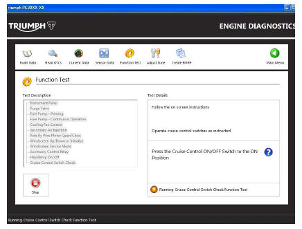
Follow the on-screen instructions to operate and then release each switch in turn.
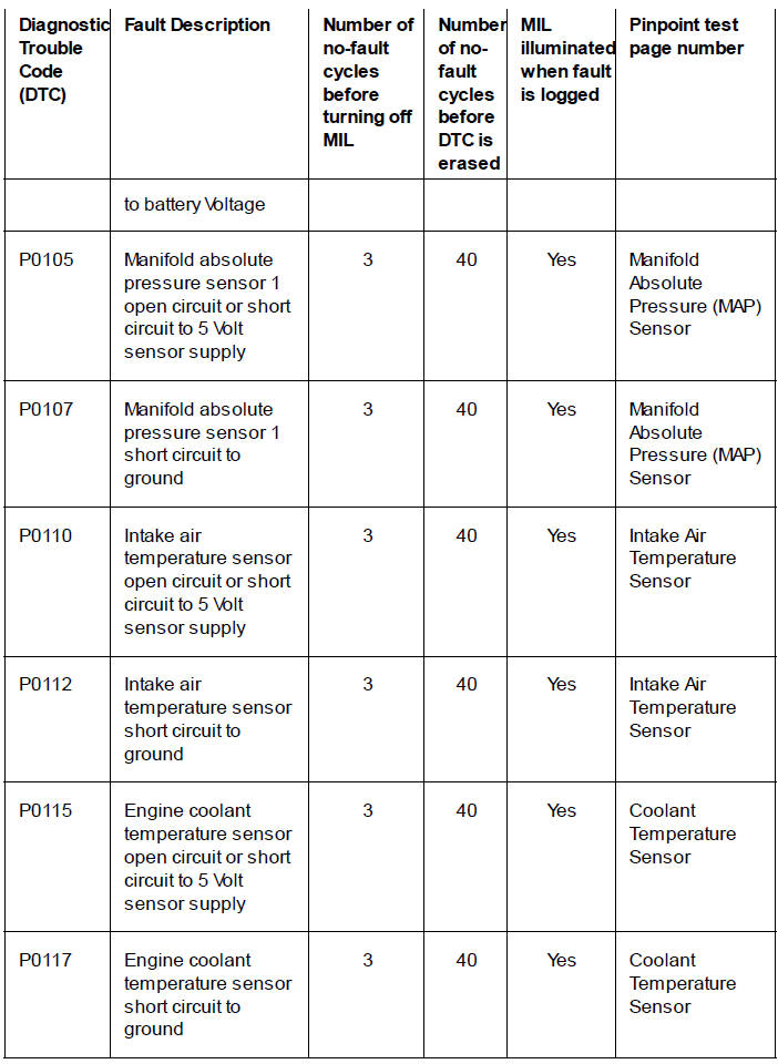
Engine Electronic Control Module - Diagnostic Trouble Codes
Diagnostic trouble codes (DTCs) are logged in the ECM memory when there is a confirmed fault in the system.
The codes are reported to the Triumph diagnostic software as a four digit code.
As mentioned earlier, when the system detects a fault, it begins to count the number of times the fault occurs before illuminating the MIL and storing a fault code.
Similarly, if a fault clears, the ECM also records this fact and will turn off the MIL when sufficient no fault warm-up cycles have taken place. Any fault codes will remain in the ECM memory until the required number of no fault warm-up cycles have taken place.
The number of warm-up cycles required to extinguish the MIL will always be less than the number required to remove a DTC from the ECM memory. DTCs can be removed at any time using the Triumph diagnostic software.
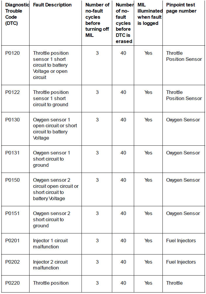
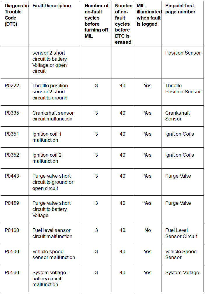
The system will log the diagnostic trouble codes listed below/over:
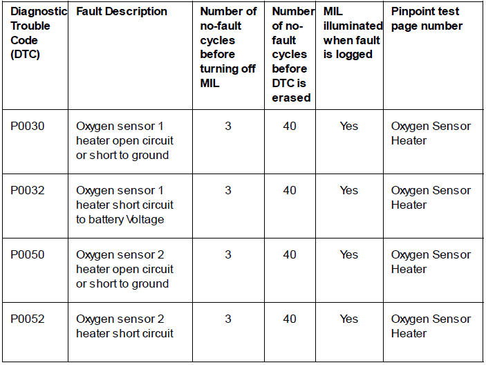
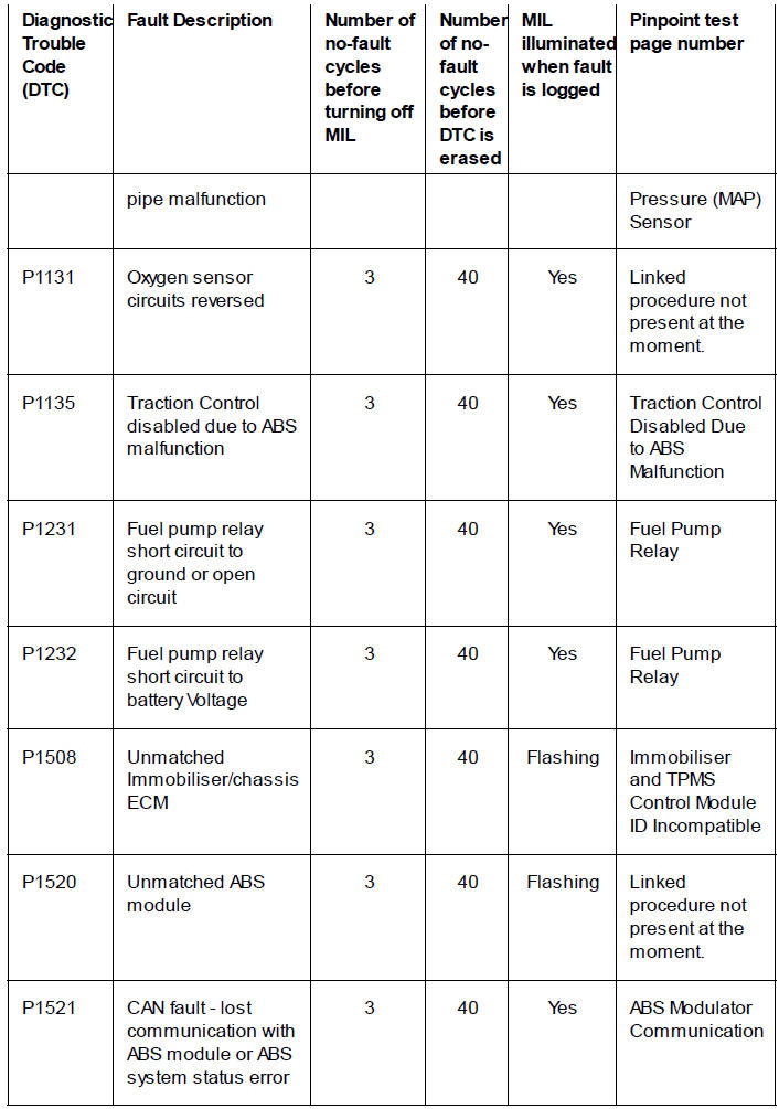
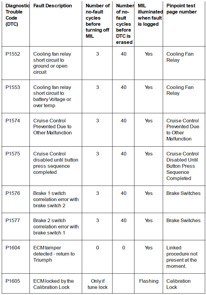
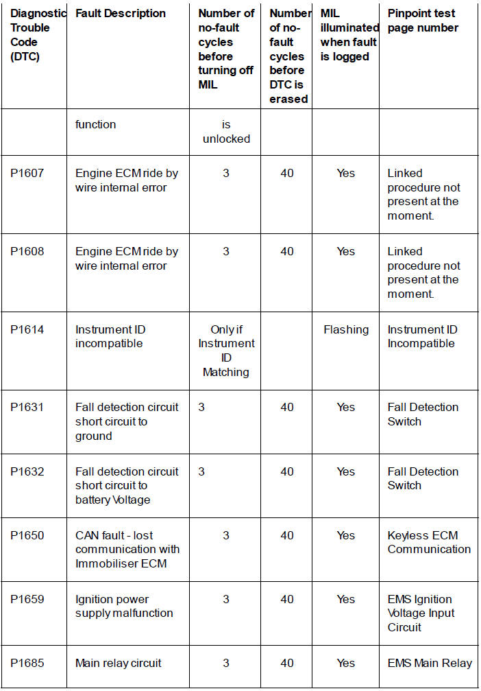
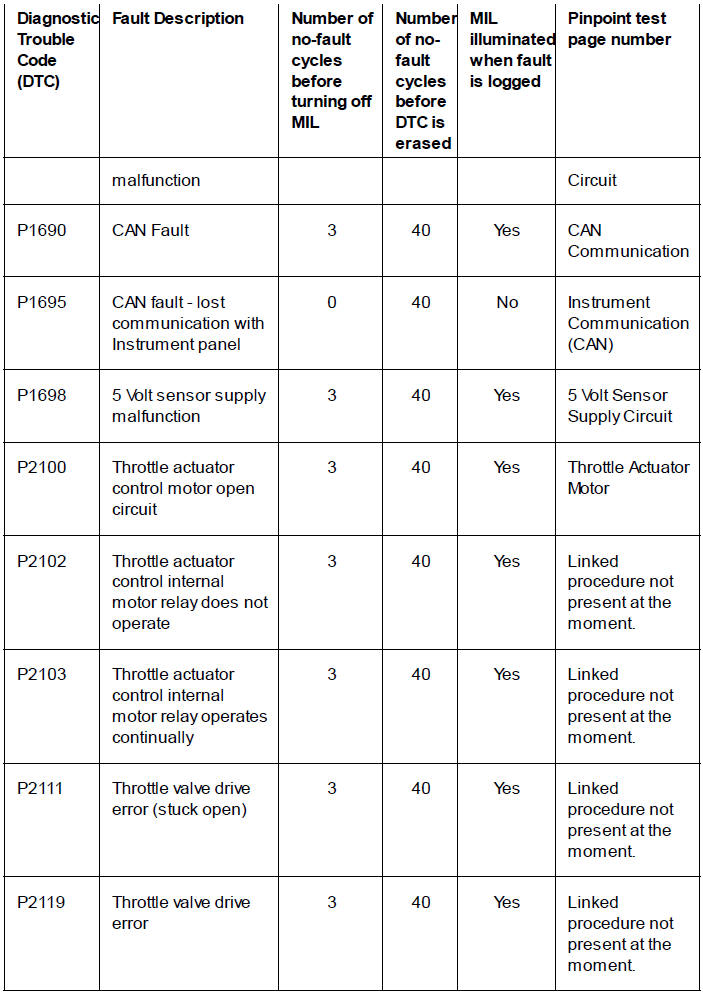
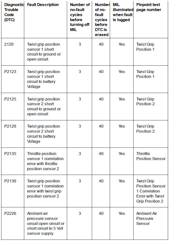
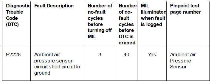
Further Diagnosis
The tables that follow will, if used correctly, help to pinpoint a fault in the system once a diagnostic trouble code has been stored.
See also:
 Triumph Scrambler 1200 XC - Service manual > Electrical Connectors
Before beginning any diagnosis, the following connector related information should be noted: Note A major cause of hidden electrical faults can be traced to faulty electrical connectors. For example: Dirty/corroded terminals Damp terminals
Triumph Scrambler 1200 XC - Service manual > Pinpoint Tests - Fuel
Oxygen Sensor Heater Pinpoint Tests
 Ducati Scrambler
 Fantic Caballero 500
 Indian FTR 1200
 Moto Guzzi V85 TT
 Royal Enfield Bullet Trials Works Replica
 Triumph Scrambler 1200 XE
 Triumph Street Scrambler
 Yamaha XSR700
 Ducati Scrambler 800
 Moto Guzzi V85 TT
 Triumph Scrambler 1200 XC