 Triumph Scrambler 1200 XC - Service manual > Engine Remove and Install
Engine - Removal
WARNING
Before starting work, ensure the motorcycle is stabilised and adequately supported. This will help prevent it from falling and causing injury to the operator or damage to the motorcycle.
Perform the following operations:
- Seat - Removal
- Battery - Removal
- Fuel Tank - Removal
- Radiator - Removal
- Sump Guard - Removal
- Cradle Assemblies - Removal
- Evaporative Canister (if fitted) - Removal
- Coolant Expansion Tank - Removal
- Exhaust Silencer - Removal, Left Hand Header Pipe - Removal and Exhaust
- Catalytic Converter - Removal
- Side Panels
- Front Sprocket Cover - Removal
- If required, drain the engine oil - Engine Oil and Filter Renew
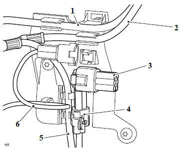
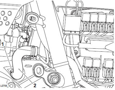
1. Disconnect the coolant hose from the thermostat housing.
2. From the top of the frame, disconnect the following electrical connectors:
- Spark plug leads
- Fuel injectors
- Coolant temperature sensor
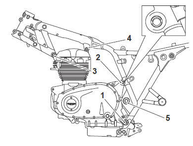
3. Disconnect the clutch cable from the crankcase (see Clutch Cable - Removal).
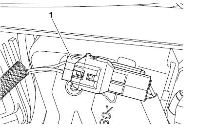
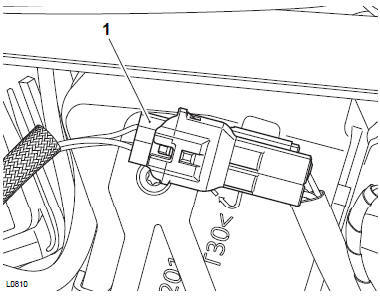
4. On the right side of the airbox, disconnect the gear position sensor electrical connector from the main harness.
Note
- To disconnect the alternator harness from the regulator/rectifier, the rear mudguard has to be removed.
- Note the routing of the alternator harness, crankshaft position sensor harness and starter motor cable for installation.
5. Remove the rear mudguard and detach the alternator harness from the regulator/rectifier (see Rear Mudguard - Removal).
6. Detach the crankshaft position sensor electrical connector from the rear of the airbox. Disconnect the crankshaft position sensor from the main harness.
7. Disconnect the starter motor lead from the starter motor solenoid.
- Crankshaft position sensor electrical connector
- Starter motor lead
8. Route the three cables down to the engine.
9. Release the two hose clips and remove the engine breather hose.
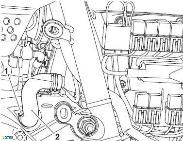
- Clips
- Engine breather pipe
10. Remove the fixing and remove the air intake finishers.
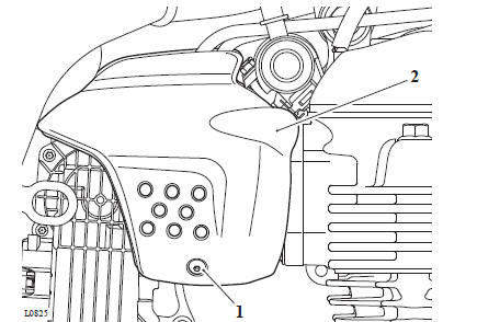
- Fixing
- Air intake finisher (right hand side shown)
11. Remove the two fixings and remove the mountings for the air intake finisher.
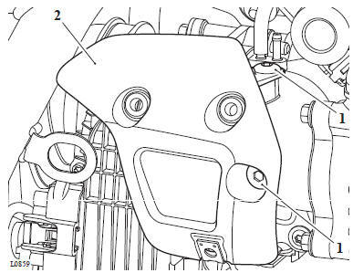
- Fixings
- Mounting (right hand side shown)
Note
Note which spigot on the inlet manifold the MAP sensor hose is fitted to and, if fitted, which spigot the evaporative emissions hose is fitted to for installation.
12. Disconnect the MAP hose and the evaporative emissions hose from the inlet manifold.
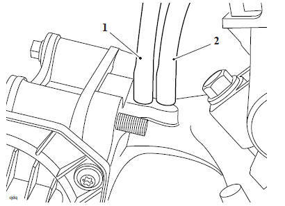
- Evaporative hose
- MAP sensor hose
13. Loosen the throttle body hose clamp.
14. Remove the four fixings securing the inlet manifold to the cylinder head and detach it from the cylinder head. Remove and discard the two seals on the inlet manifold.
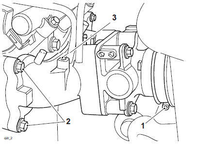
- Clamp
- Inlet manifold fixings (left hand side)
- Inlet manifold
15. Remove the fixings and remove the right hand heel guard.
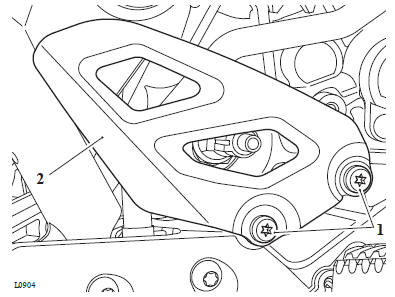
- Fixings
- Heel guard
WARNING
Do not allow a brake component to hang unsupported on the brake hose or line.
Brake hoses or lines that are not supported may become damaged or bent.
Bent or damaged brake hoses or lines lead to reduced braking efficiency causing loss of motorcycle control and an accident.
CAUTION
To prevent paint damage, do not spill brake fluid onto any area of the bodywork.
Spilled brake fluid will damage paintwork.
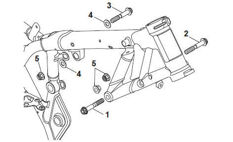
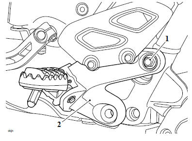
16. Release the fixings and detach the right hand control plate from the frame.
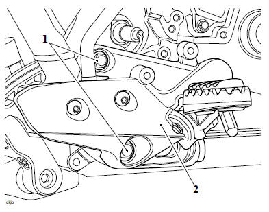
- Fixings
- Right hand control plate
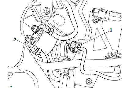
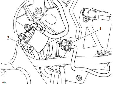
17. Disconnect the oil pressure switch electrical connector.
- Electrical connector
18. Loosen the drive chain and remove it from the front sprocket (see Final Drive Chain Adjustment).
19. From the left hand side, disconnect the engine earth strap.
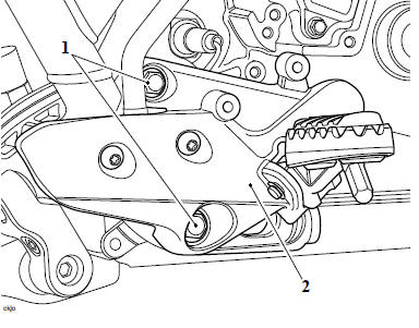
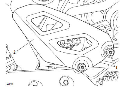
20. Release the fixing and remove the left hand control plate.
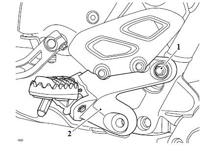
- Fixing
- Left hand control plate
21. Carefully remove the swinging arm pivot cover on the left hand side of the frame.
22. Remove the swinging arm pivot nut and collect the washer on the left hand side of the frame.
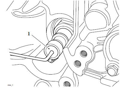
23. Partially remove the swinging arm spindle to access the frame adjuster sleeve.
24. Engage T3880104 - Swinging Arm Adjuster Wrench in the slots of the frame adjuster sleeve and rotate anticlockwise to loosen the sleeve fully.
- Frame adjuster
- T3880104 - Swinging Arm Adjuster Wrench
25. Place a support beneath the engine and ensure that the frame is still adequately and securely supported.
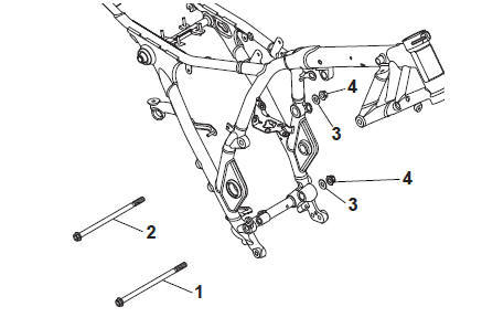
26. Release the engine mounting nuts. Collect the nuts and washers, leaving the bolts in position.
27. Remove the left hand cylinder head mounting bolt.
28. Remove the cylinder head rear mounting bolt.
29. Using T3880377 - Engine Mounting Adjuster release the:
- Rear cylinder head mounting adjuster on the left side of the frame.
- Upper rear crankcase mounting adjuster.
- Lower rear crankcase mounting adjuster.
- Left hand cylinder head mounting adjuster.
30. Remove the right hand cylinder head mounting bolt.
31. Remove the remaining mounting bolts, collecting the spacer from the lower crankcase mounting bolt.
CAUTION
Three brake lines, the rear brake switch harness, rear wheel ABS sensor and the bluetooth connector are attached to the brake line tidy on the rear of the crankcase.
Failure to detach the brake lines or harnesses from the brake line tidy will cause damage to the braking system.
Note the routing of the components attached to the brake line tidy for installation.
32. While carefully lowering the engine, detach the brake lines and harnesses from the brake line tidy and position away from the crankcase.
- Brake line (front brake master cylinder)
- Brake line (front brake calipers)
- Bluetooth connector
- Rear brake light switch harness
- Brake line (rear brake master cylinder)
- Rear wheel ABS sensor
Engine - Installation
WARNING
Before starting work, ensure the motorcycle is stabilised and adequately supported. This will help prevent it from falling and causing injury to the operator or damage to the motorcycle.
1. While carefully locating the engine to the frame, attach the brake lines and harnesses to the brake line tidy as noted for removal.
- Brake line (front brake master cylinder)
- Brake line (front brake calipers)
- Bluetooth connector
- Rear brake light switch harness
- Brake line (rear brake master cylinder)
- Rear wheel ABS sensor
2. Align the engine mounting points with the corresponding positions on the frame.
3. Install and tighten the engine mounting bolts in the following 3 stages.
4. Stage 1
- Insert the cylinder head left hand front mounting bolt with washer between the bolt and the frame.
- Insert the cylinder head right hand front mounting bolt. Fit a new lock nut but do not fully tighten at this stage.
- Fit the spacer between the crankcase and the frame on the right hand side. Insert the crankcase rear lower mounting bolt from the right hand side. Do not fit the washer and new lock nut at this stage.
- Insert the crankcase rear upper mounting bolt from the right hand side. Do not fit the washer and new lock nut at this stage.
- Insert the cylinder head rear mounting bolt and washer from the left hand side.
5. Stage 2
6. Partially withdraw the crankcase rear lower mounting bolt and tighten the frame adjuster to 5 Nm using T3880377 - Engine Mounting Adjuster. Refit the bolt and washer.
7. Partially withdraw the crankcase rear upper mounting bolt and tighten the frame adjuster to 5 Nm using T3880377 - Engine Mounting Adjuster. Refit the bolt and washer.
8. Counter hold the cylinder head front right hand mounting nut and tighten the bolt to 24 Nm.
9. Withdraw the cylinder head left hand mounting bolt and its washer, tighten the frame adjuster to 5 Nm using T3880377 - Engine Mounting Adjuster. Insert the washer and bolt with washer between the bolt and the frame.
10. Withdraw the cylinder head rear mounting bolt and tighten the frame adjuster to 5 Nm using T3880377 - Engine Mounting Adjuster.
- Lower rear crankcase adjuster
- Upper rear crankcase adjuster
- Left hand cylinder head frame adjuster
- Rear cylinder head frame adjuster
- Swinging arm adjuster
11. Fit the washer and a new lock nut to the crankcase lower rear mounting bolt.
Counter hold the bolt and tighten the nut to 80 Nm.
12. Fit the washer and a new lock nut to the crankcase upper rear mounting bolt.
Counter hold the bolt and tighten the nut to 80 Nm.
- Crankcase lower rear mounting bolt
- Crankcase upper rear mounting bolt
- Washer
- Lock nut
13. Counter hold the nut and tighten the cylinder head front right hand mounting bolt to 105 Nm.
14. Fit the washer and a new lock nut to the cylinder head front left hand mounting bolt. Counter hold the nut and tighten the bolt to 105 Nm.
15. Fit the washer and a new lock nut to the cylinder head rear mounting bolt. Counter hold the nut and tighten the bolt to 105 Nm.
- Cylinder head front right hand mounting bolt
- Cylinder head front left hand mounting bolt
- Cylinder head rear mounting bolt
- Washer
- Lock nut
16. Stage 3
17. Using T3880104 - Swinging Arm Adjuster Wrench, tighten the swinging arm pivot bolt adjuster sleeve to 6 Nm.
18. Fit the washer and a new lock nut to the swinging arm spindle. Counter hold the spindle and tighten the nut to 110 Nm.
19. Refit the swinging arm pivot cover to the left hand side of the frame.
20. On the left hand side, connect the engine ground cable.
Refit the rider's left hand control plate, fit the upper fixing only and do not fully tighten at this stage.
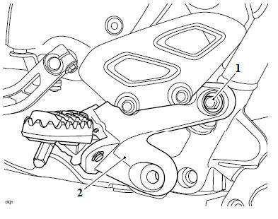
- Fixing
- Left hand control plate
22. Refit the drive chain to the front sprocket and adjust (see Final Drive Chain Adjustment).
23. Connect the oil pressure switch electrical connector.
- Electrical connector
WARNING
Do not allow a brake component to hang unsupported on the brake hose or line.
Brake hoses or lines that are not supported may become damaged or bent.
Bent or damaged brake hoses or lines lead to reduced braking efficiency causing loss of motorcycle control and an accident.
CAUTION
To prevent paint damage, do not spill brake fluid onto any area of the bodywork.
Spilled brake fluid will damage paintwork.
24. Refit the rider's right hand control plate, fit the upper fixing only and do not fully tighten at this stage.
- Upper fixing
- Right hand control plate
25. Refit the engine breather hose and secure with the hose clips.
- Clips
- Engine breather pipe
26. Route the alternator harness, crankshaft position sensor harness and starter motor leads as noted for removal.
27. Connect the starter motor lead to the starter motor solenoid and tighten the fixing to 5 Nm.
28. Connect the crankshaft position sensor to the main harness and attach the connector to the rear of the airbox.
- Crankshaft position sensor electrical connector
- Starter motor lead
29. Connect the alternator harness to the regulator/rectifier and refit the rear mudguard (see Rear Mudguard - Installation).
30. On the right side of the airbox, connect the gear position sensor electrical connector to the main harness.
31. Connect the clutch cable to the crankcase and clutch (see Clutch Cable - Installation).
32. Ensure the mating surfaces on the inlet manifold and the cylinder head are clean.
33. Fit two new seals to the mating surfaces of the inlet manifold.
34. Fit the inlet manifold to the cylinder head.
35. Tighten the inlet manifold to cylinder head fixings to 9 Nm in the sequence shown below.
36. Retighten the fixings one and two to 9 Nm.
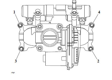
Tightening Sequence
37. Ensure the throttle body hose is correctly fitted and tighten the clip to 1.5 Nm.
38. Connect the MAP hose and the evaporative emissions hose to the inlet manifold, as noted for removal.
39. Fit the mountings for the air intake finisher and tighten its fixings to 3 Nm.
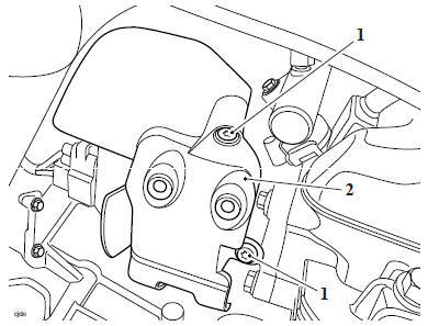
- Fixings
- Mounting (right hand side shown)
40. Fit the air intake finishers and tighten the fixing to 1.5 Nm.
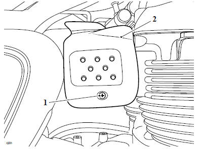
- Fixing
- Air intake finisher (right hand side shown)
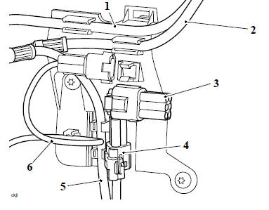
41.Connect the following electrical connectors:
- Coolant temperature sensor.
- Fuel injectors
- Spark plug leads
42. Refit the coolant hose to the thermostat housing and secure using T3880207 - Hose Clip Pliers.
43. Refit the side panels (see Side Panels).
44. Refit the exhaust catalytic system (see Exhaust Catalytic Converter - Installation, Left Hand Header Pipe - Installation and Exhaust Silencer - Installation).
45. Refit the cradle assemblies (see Cradle Assemblies - Installation).
46. Tighten the rider's right hand control plate upper fixing to 25 Nm.
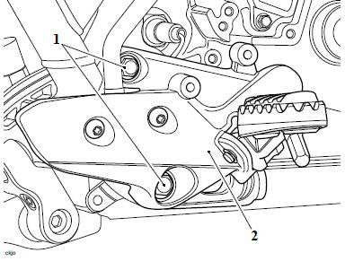
- Upper fixing
- Right hand control plate
47. Refit the right hand heel guard and tighten its fixings to 7 Nm.
- Fixings
- Heel guard
48. Tighten the rider's left hand control plate upper fixing to 25 Nm.
- Fixing
- Left hand control plate
Perform the following operations:
- Front Sprocket Cover - Installation
- Coolant Expansion Tank - Installation
- Evaporative Canister (if fitted) - Installation
- Radiator - Installation
- Sump Guard - Installation
- Fuel Tank - Installation
- Battery - Installation
- Seat - Installation
- If required, refill the engine with engine oil - Engine Oil and Filter Renew
- Reset the neutral position adaption (see Neutral Position Adaption).
See also:
 Triumph Scrambler 1200 XC - Service manual > Lubrication
Exploded View - Oil Filter and Pump Oil Circuit Diagram
 Ducati Scrambler
 Fantic Caballero 500
 Indian FTR 1200
 Moto Guzzi V85 TT
 Royal Enfield Bullet Trials Works Replica
 Triumph Scrambler 1200 XE
 Triumph Street Scrambler
 Yamaha XSR700
 Ducati Scrambler 800
 Moto Guzzi V85 TT
 Triumph Scrambler 1200 XC