 Triumph Scrambler 1200 XC - Service manual > Lubrication
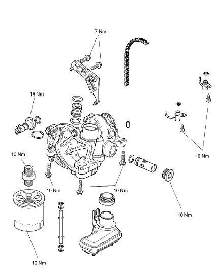
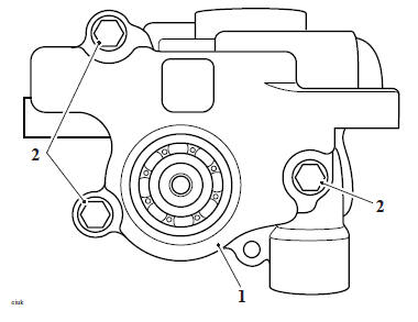
Exploded View - Oil Filter and Pump
Oil Circuit Diagram
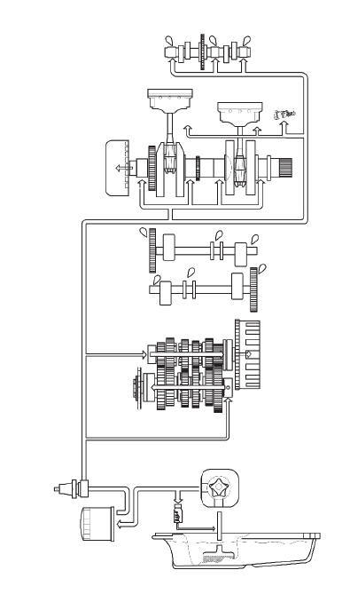
Oil Circuit
Oil is collected from the sump and is drawn through a mesh strainer into the oil pump rotor. The oil pump is fitted with a single pumping rotor assembly which supplies pressurised oil to the lubrication circuit. The oil circuit is split into two parts - the Main circuit and the Transmission circuit.
Main Circuit
Pressurised oil flows past the oil pressure relief valve, which controls the maximum pressure in the oil circuit. The relief valve is set to open at 5.1 bar (74 lb/in²) and when open, returns high pressure oil directly to the oil pump inlet port.
The oil then flows through the oil filter. Filtered oil is then fed into the lower crankcase gallery. The low oil pressure switch is located in this gallery.
From here oil is distributed around the engine:
- A branch supplies oil to the main gallery below the main bearings. Here it is delivered to the crankshaft main bearings and, via drillings in the crankshaft, to the big end bearings.
- Oil is also fed to the alternator to aid cooling of the alternator. The oil is taken from the crankshaft oil feed and directed to the alternator stator and rotor.
- Spray jets located in the upper crankcase, above the front balance shaft, lubricate the pistons and connecting rod small ends. These jets are fed oil from the cylinder head oil feed.
- Another branch from the cylinder head oil feed supplies oil to the hydraulic camshaft drive chain tensioner.
- Oil is sent to the cylinder head via a drilling in the upper crankcase.
From the
crankcase the oil divides into the two front cylinder head bolt drilling's,
up through
the cylinder barrels and into the cylinder head. One of the bolt drilling's
feeds the
left hand cam shaft frame and the other feeds the right hand camshaft frame.
Drillings and grooves in the camshaft frames allow oil to flow to the camshaft journals and rocker shafts. Oil from the cylinder head area lubricates the camshaft drive chain before draining back to the sump.
Transmission Circuit
- Pressurised oil is directed via drillings to the input and output shafts and the clutch. Oil is circulated along the gearbox shafts to exit holes that feed directly to the bearings and gears before draining back to the sump.
- The selector drum is splash fed by oil returning to the sump from the transmission gears.
Triumph Engine Oil
Your Triumph motorcycle is a quality engineered product which has been carefully built and tested to exacting standards. Triumph Motorcycles are keen to ensure that you enjoy optimum performance from your motorcycle and with this objective in mind have tested many of the engine lubricants currently available to the limits of their performance.
Engine Oil - Specification
Use semi or fully synthetic 10W/40 or 10W/50 motorcycle engine oil which meets specification API SH (or higher) and JASO MA, such as Castrol Power 1 Racing 4T, sold as Castrol Power RS Racing 4T in some countries.
Triumph recommends the fully synthetic 10W/40 motorcycle engine oil for most conditions. The oil viscosity may need to be changed to accommodate the ambient temperatures in your riding area.
Refer to the chart below for the correct oil viscosity (10W/40 or 10W/50) to be used in your riding area.
Oil Viscosity Temperature Range
CAUTION
Triumph high performance fuel injected engines are designed to use semi or fully synthetic motorcycle engine oil which meets specification API SH (or higher) and JASO MA.
Do not add any chemical additives to the engine oil. The engine oil also lubricates the clutch and any additives could cause the clutch to slip.
Do not use mineral, vegetable, non-detergent oil, castor based oils or any oil not conforming to the required specification. The use of these oils may cause instant, severe engine damage.
Ensure no foreign matter enters the crankcase during an oil change or top up.
Disposal of Used Engine Oil and Oil Filters
To protect the environment, do not pour oil on the ground, down sewers or drains, or into watercourses. Do not place used oil filters in with general waste. If in doubt contact your local authority.
Oil and Water Pump - Removal
WARNING
Before starting work, ensure the motorcycle is stabilised and adequately supported. This will help prevent it from falling and causing injury to the operator or damage to the motorcycle.
WARNING
Prolonged or repeated contact with engine oil can lead to skin dryness, irritation and dermatitis. In addition, used engine oil contains potentially harmful contamination which can cause cancer. Wear suitable clothing and avoid skin contact.
The engine oil and filter must be replaced in accordance with scheduled maintenance requirements.
Note
- The oil pump and water pump are supplied as an assembly and cannot be separated. This procedure covers the removal of the oil and water pump assembly.
CAUTION
Do not pour engine oil on the ground, down sewers or drains, or into watercourses. To prevent pollution of watercourses etc., dispose of used oil sensibly. If in doubt contact your local authority.
Perform the following operations:
- Seat - Removal
- Battery - Removal
- Drain the coolant Coolant Replacement - Drainage
- Drain the engine oil Engine Oil and Filter Renew
Sump - Removal
Clutch - Removal
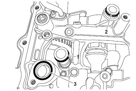
1. Release the oil pick-up from the oil seal.
2. Remove and discard the oil seal.
- Oil pick-up
- Oil seal
3. Slide the oil pump drive sprocket gently backwards and forwards to release the needle roller bearing.
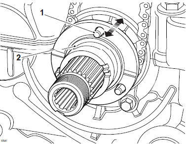
- Oil pump drive sprocket
- Needle roller bearing
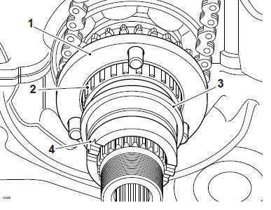
4. Support the oil pump drive sprocket and carefully remove the bush, spacer and needle roller bearing while noting it's orientation.
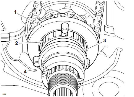
- Oil pump drive sprocket
- Needle roller bearing
- Spacer
- Bush
5. Release and discard the fixings securing the oil and water pump.
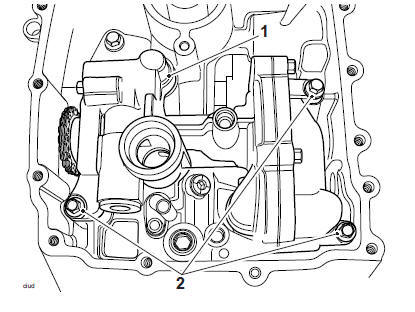
- Oil and water pump
- Fixings
6. Detach the drive chain from the oil pump drive sprocket.
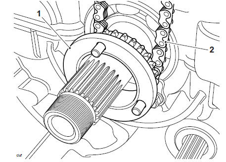
- Oil pump drive sprocket
- Drive chain
7. Carefully withdraw the oil and water pump from the crankcase.
Note
The water pump inlet sleeve/O-rings can become dislodged during removal of the oil pump.
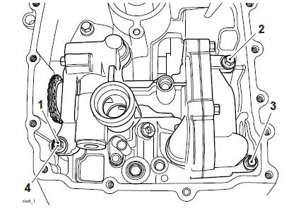
8. Remove the coolant outlet sleeve and the oil pump outlet sleeve from the crankcase.
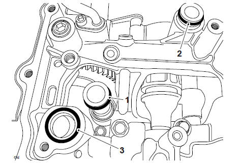
- Coolant outlet sleeve
- Oil outlet sleeve
- Coolant inlet seal
9. Remove and discard the four O-rings from the coolant outlet sleeve and then remove and discard the two O-rings from the oil outlet sleeve.
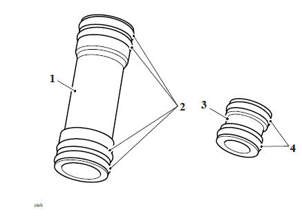
- Coolant outlet sleeve
- O-ring (coolant)
- Oil outlet sleeve
- O-ring (oil)
10. Remove and discard the coolant inlet O-ring from the crankcase.
- O-ring (coolant inlet)
Oil Pump Inspection
1. Inspect the sprocket and chain for wear and/or damage. Replace the pump and chain if wear is found.
2. Check the shaft and shaft bearings for side and end float. Replace the pump if wear is found.
3. Carry out a visual inspection for corrosion and scale build-up around the coolant pump impeller and in the coolant pump body. Replace the pump assembly if necessary.
Oil Pump - Disassembly
1. Using T3880603 - Oil Pump Restraint release the fixing and remove the drive sprocket and spacer washer.
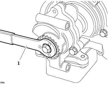
- T3880603 - Oil Pump Restraint
2. Release the three fixings and withdraw the oil pump end plate.
- Oil pump end plate
- Fixings
CAUTION
If any part of the oil pump is found to be outside the service limit, the complete pump must be replaced. Severe engine damage may result from the continued use of a faulty oil pump.
Oil Pump Inspection
1. Inspect the sprocket and chain for wear and/or damage. Replace the pump and chain if wear is found.
2. Check the shaft and shaft bearings for side and end float. Replace the pump if wear is found.
3. Carry out a visual inspection for corrosion and scale build-up around the coolant pump impeller and in the coolant pump body. Replace the pump assembly if
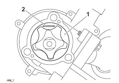
Oil Pump Rotor Tip Clearance
1. Measure the rotor tip clearance using feeler gauges.
2. For specifications refer toLubrication.
Rotor Tip Clearance
Oil Pump Body Clearance
1. Measure the pump body clearance using feeler gauges.
2. For specifications refer toLubrication.
Pump Body Clearance
Oil Pump End Clearance
1. Remove the endplate from the pump.
2. Wipe the exposed areas of the rotors and the machined face of the end plate.
Note
The oil pump end clearance is measured using Plastigauge (Triumph part number 3880150-T0301). Do not turn the oil pump during the clearance measurement as this will damage the 'Plastigauge'.
3. Apply a thin smear of grease to the rotor and a small quantity of silicone release agent to the face of the end plate.
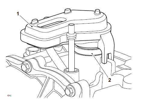
4. Cut a length of the Plastigauge to fit across the rotor. Fit the strip to the rotor using the grease to hold the Plastigauge in place.
- Outer rotor
- Plastigauge
5. Without any twisting action, refit the oil pump cover and tighten its fixings to 10 Nm.
6. Release the bolts and carefully remove the end plate.
7. Using the gauge provided with the Plastigauge kit, measure the width of the compressed Plastigauge.
8. For specifications refer toLubrication.
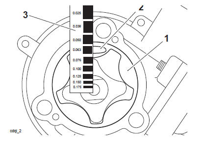
1. Rotor (outer) 2. Plastigauge 3. Gauge, in millimetres
9. If the clearance measured is within the specified tolerance, clean off all traces of Plastigauge from the outer rotor and oil pump cover.
10. If any clearance measured is outside the service limits, renew the complete pump.
Oil Pump - Assembly
1. If all clearances are within service limits, liberally apply clean engine oil to all internal components and refit the rotor to the oil pump body.
2. Refit the end plate. Apply ThreeBond 1374 to the fixings, refit and tighten to 10 Nm.
- Oil pump end plate
- Fixings
3. Refit the spacer washer and drive sprocket. Apply ThreeBond 1374 to the fixing and tighten to 12 Nm.
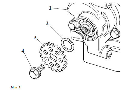
- Oil pump
- Spacer washer
- Drive sprocket
- Fixing
Oil and Water Pump - Installation
CAUTION
Before fitting the pump to the crankcase ensure the pump internal surfaces have been wetted with clean engine oil. The pump may fail to pick up oil from the sump if the surfaces have not been wetted. This will cause the engine to run without engine oil pressure and will lead to severe engine damage.
1. Install four new O-rings to the water pump outlet sleeve.
2. Install two new O-rings to the oil pump outlet sleeve.
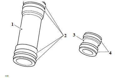
- Coolant outlet sleeve
- O-ring (coolant)
- Oil outlet sleeve
- O-ring (oil)
3. Fit the coolant outlet sleeve, the oil outlet sleeve and the coolant inlet O-ring to the crankcase.
- Coolant outlet sleeve
- Oil outlet sleeve
- O-ring (coolant inlet)
4. Fill the oil pump with new engine oil, turning the pump rotor as the oil is poured in to ensure all surfaces are coated with oil.
5. Position the oil and water pump to the crankcase inserting the oil pump outlet sleeve and the water pump outlet sleeve into the openings.
CAUTION
Do not use excessive force to insert the outlet sleeves into the oil pump. Severe oil pump or outlet sleeve damage may result from the use of excessive force.
6. Feed the drive chain over the transmission input shaft and fit to the sprocket.
7. Fit the drive chain on to the oil pump sprocket.
8. Refit the oil and water pump. Install new fixings and tighten to 10 Nm in the sequence shown below.
Tightening Sequence
9. Support the oil and water pump drive sprocket and carefully refit the bush spacer and needle roller bearing as noted during removal.
- Drive sprocket
- Needle roller bearing
- Spacer
- Bush
10. Install a new oil seal and refit the oil pick-up.
- Oil pick-up
- Oil seal
Perform the following operations:
- Clutch - Installation
- Sump - Installation
- Engine Oil and Filter Renew
- Coolant Replacement - Filling
- Battery - Installation
- Seat - Installation
Oil Pressure Relief Valve - Removal
WARNING
Before starting work, ensure the motorcycle is stabilised and adequately supported. This will help prevent it from falling and causing injury to the operator or damage to the motorcycle.
WARNING
Prolonged or repeated contact with engine oil can lead to skin dryness, irritation and dermatitis. In addition, used engine oil contains potentially harmful contamination which can cause cancer. Wear suitable clothing and avoid skin contact.
The engine oil and filter must be replaced in accordance with scheduled maintenance requirements.
The oil pressure relief valve is located in the oil pump housing. It is positioned behind a threaded blanking plug in the oil pump body.
Perform the following operations:
- Seat - Removal
- Battery - Removal
- Sump - Removal
WARNING
The oil may be hot to the touch. Contact with hot oil may cause the skin to be scalded or burned.
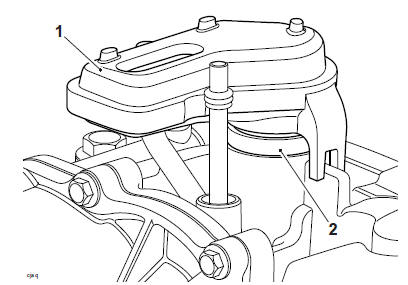
1. Removethe blanking plug.
- Blanking plug
2. Carefully withdraw the oil pressure relief valve from the oil pump housing.
3. Remove and discard the O-ring from the oil pressure relief valve.
Oil Pressure Relief Valve - Installation
1. Lubricate the new O-ring with clean engine oil and fit to the oil pressure relief valve.

- Oil pressure relief valve
- O-ring
2. Refit the oil pressure relief valve as noted during removal.
3. Refit the blanking plug and tighten to 10 Nm.
4. Refit the sump, ensuring the water pump drain tube is correctly installed (see Sump - Installation).
Perform the following operations:
Battery - Installation
Seat - Installation
Low Oil Pressure Warning Light Switch - Removal
WARNING
Before starting work, ensure the motorcycle is stabilised and adequately supported. This will help prevent it from falling and causing injury to the operator or damage to the motorcycle.
WARNING
Prolonged or repeated contact with engine oil can lead to skin dryness, irritation and dermatitis. In addition, used engine oil contains potentially harmful contamination which can cause cancer. Wear suitable clothing and avoid skin contact.
The engine oil and filter must be replaced in accordance with scheduled maintenance requirements.
CAUTION
Do not pour engine oil on the ground, down sewers or drains, or into watercourses. To prevent pollution of watercourses etc., dispose of used oil sensibly. If in doubt contact your local authority.
The low oil pressure warning light switch is located in the lower crankcase, behind the sprocket cover.
- Front Sprocket Cover - Removal
WARNING
Do not allow a brake component to hang unsupported on the brake hose or line.
Brake hoses or lines that are not unsupported may become damaged or bent.
Bent or damaged brake hoses or lines lead to reduced braking efficiency causing loss of motorcycle control and an accident.
1. Remove the fixings and remove the right hand heel guard.
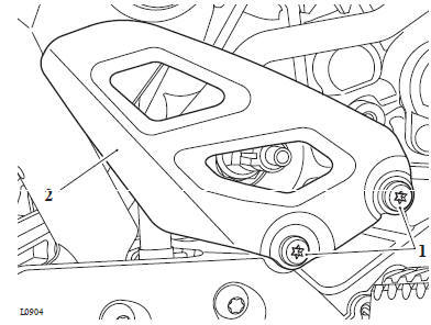
- Fixings
- Heel guard
2. Disconnect the electrical connector.
Note
A small amount of oil will drain from the oil gallery when the switch is removed.
3. Position a suitable receptacle to collect any displaced oil from the oil gallery.
4. Remove the switch and discard the sealing washer.
- Low oil pressure warning light switch
Low Oil Pressure Warning Light Switch - Installation
1. Incorporating a new sealing washer, fit the low oil pressure light switch.
2. Tighten the switch to 15 Nm.
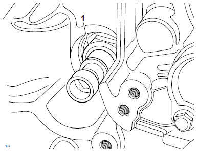
1. Low oil pressurewarning light switch
3. Reconnect the electrical connector.
4. Refit the right hand heel guard and tighten the fixings to 7 Nm.
5. Refit the sprocket cover (see Front Sprocket Cover - Installation).
6. Reconnect the battery positive, (red) lead first (see Battery - Installation) and tighten the terminals to 4.5 Nm.
7. Start the engine and ensure that the oil pressure warning light extinguishes shortly after starting.
8. Allow the engine to idle for a minimum of 30 seconds.
CAUTION
If the engine oil pressure is too low, the low oil pressure warning light will illuminate. If this light stays on when the engine is running, stop the engine immediately and investigate the cause. Running the engine with low oil pressure will cause engine damage.
9. Stop the engine and check the oil level as described (see Engine Oil - Level Inspection). Adjust if necessary.
Perform the following operations:
- Seat - Installation
See also:
 Triumph Scrambler 1200 XC - Service manual > Starter Drive and Sprag Clutch
Exploded View - Starter and Sprag Starter Drive/Sprag Clutch - Removal
Triumph Scrambler 1200 XC - Service manual > Engine Remove and Install
Engine - Removal WARNING Before starting work, ensure the motorcycle is stabilised and adequately supported. This will help prevent it from falling and causing injury to the operator or damage to the motorcycle.
 Ducati Scrambler
 Fantic Caballero 500
 Indian FTR 1200
 Moto Guzzi V85 TT
 Royal Enfield Bullet Trials Works Replica
 Triumph Scrambler 1200 XE
 Triumph Street Scrambler
 Yamaha XSR700
 Ducati Scrambler 800
 Moto Guzzi V85 TT
 Triumph Scrambler 1200 XC