 Moto Guzzi V85 TT - Service manual > Front side
TABLE A - VOLTAGE REGULATOR ASSEMBLY
- Regulator side flywheel cable
- Regulator cable to wiring harness
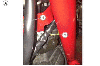
TABLE A1 - VOLTAGE REGULATOR ASSEMBLY
- Medium clamps (previously mounted)
- Engine side flywheel cable
- Regulator side flywheel cable
- Horn cable
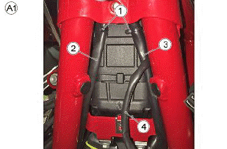
TABLE A2 - VOLTAGE REGULATOR ASSEMBLY
- Horn connectors
- Horn
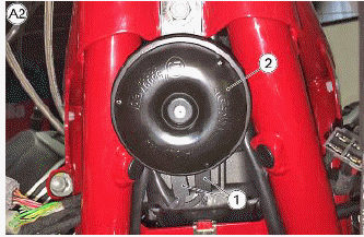
TABLE A3 - VOLTAGE REGULATOR ASSEMBLY
- Position the excess cable as illustrated in the figure
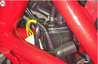
TABLE A4 - VOLTAGE REGULATOR ASSEMBLY
- Voltage regulator
Fasten the voltage regulator as illustrated in the figure
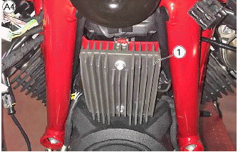
TABLE B - INSTRUMENT CLUSTER PRE-ASSEMBLY AND ASSEMBLY ON THE BIKE
- Air temperature sensor
Assemble the external air temperature sensor as the first operation
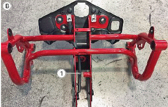
TABLE B1 - INSTRUMENT CLUSTER PRE-ASSEMBLY AND ASSEMBLY ON THE BIKE
- Plug socket with rubber piece
- Air temperature sensor
Assemble the turn indicators and run the wiring in the frame pipes
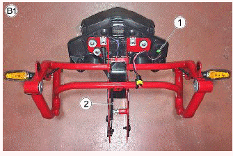
TABLE B2 - INSTRUMENT CLUSTER PRE-ASSEMBLY AND ASSEMBLY ON THE BIKE
- Support for AMP connection
- Small clamp
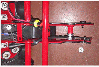
TABLE B3 - INSTRUMENT CLUSTER PRE-ASSEMBLY AND ASSEMBLY ON THE BIKE
- Plug socket with rubber piece
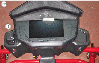
TABLE B4 - INSTRUMENT CLUSTER PRE-ASSEMBLY AND ASSEMBLY ON THE BIKE
- Small clamp
Air temperature sensor fastenings
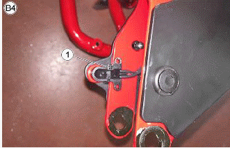
TABLE B5 - INSTRUMENT CLUSTER PRE-ASSEMBLY AND ASSEMBLY ON THE BIKE
- Front right turn indicator connector
- Front left turn indicator connector
Run the connections in the instrument cluster head
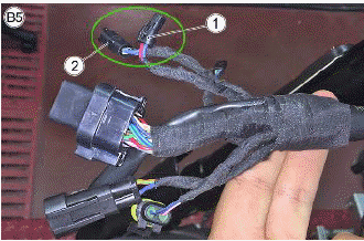
TABLE B6 - INSTRUMENT CLUSTER PRE-ASSEMBLY AND ASSEMBLY ON THE BIKE
- Wiring to the instrument cluster
- Small clamp
- Front speed sensor wiring
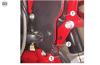
TABLE B7 - INSTRUMENT CLUSTER PRE-ASSEMBLY AND ASSEMBLY ON THE BIKE
- Air temperature sensor connection
- Power socket connection with rubber piece
Both connections are objectivated with brackets for AMP connections
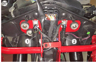
TABLE B8 - INSTRUMENT CLUSTER PRE-ASSEMBLY AND ASSEMBLY ON THE BIKE
- Instrument panel connector
- Front headlamp connector
Assemble the front light cluster and, after connecting it, fastened the connector to the frame support as illustrated in the figure
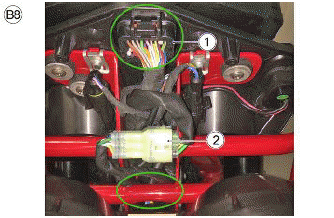
TABLE C - FRONT TURN INDICATORS
- Right turn indicator connection
During installation one wire must be covered and the other with sheath
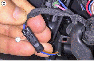
TABLE C1 - FRONT TURN INDICATORS
- Left turn indicator connection
During installation one wire must be covered and the other with sheath
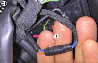
TABLE C2 - FRONT TURN INDICATORS
- Proceed as indicated in the figure
Once the turn connectors are connected, fasten the cables behind the instrument cluster
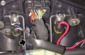
TABLE D - HANDLEBAR
- Rubber cable guide
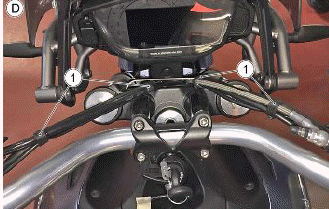
TABLE D1 - HANDLEBAR
- Front stop switch
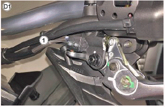
TABLE D2 - HANDLEBAR
- Right light switch
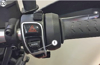
TABLE D3 - HANDLEBAR
- Left light switch
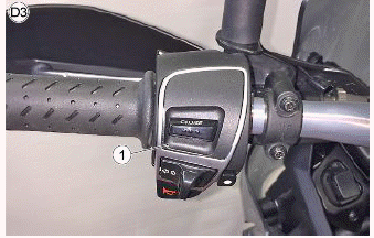
TABLE D4 - HANDLEBAR
- Clutch switch
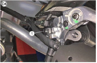
TABLE E - FRONT WHEEL SPEED SENSOR
- Front speed sensor
- Speed sensor fastening
- Cable gland
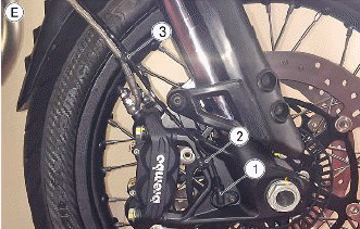
TABLE E1 - FRONT WHEEL SPEED SENSOR
- Cable gland
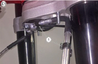
TABLE E2 - FRONT WHEEL SPEED SENSOR
- Cable gland
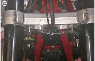
TABLE E3 - FRONT WHEEL SPEED SENSOR
- Clip
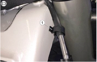
TABLE E4 - FRONT WHEEL SPEED SENSOR
- Speed sensor cable
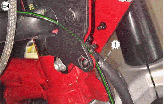
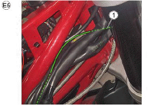
TABLE E5 - FRONT WHEEL SPEED SENSOR
- Speed sensor cable
See also:
 Moto Guzzi V85 TT - Service manual > Electrical system installation
TABLE C - PRELIMINARY PHASE Proceed as indicated in the figure
Moto Guzzi V85 TT - Service manual > Central part
TABLE A - RIGHT INJECTOR CABLE ROUTING Right injector connector The cable must run as illustrated in the figure
 Ducati Scrambler
 Fantic Caballero 500
 Indian FTR 1200
 Moto Guzzi V85 TT
 Royal Enfield Bullet Trials Works Replica
 Triumph Scrambler 1200 XE
 Triumph Street Scrambler
 Yamaha XSR700
 Ducati Scrambler 800
 Moto Guzzi V85 TT
 Triumph Scrambler 1200 XC