 Moto Guzzi V85 TT - Service manual > Central part
TABLE A - RIGHT INJECTOR CABLE ROUTING
- Right injector connector
The cable must run as illustrated in the figure
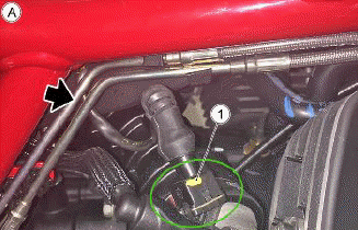
TABLE A1 - LEFT INJECTOR CABLE ROUTING
- Left injector connector
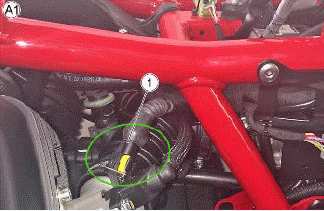
TABLE B - FILTER BOX AND THROTTLE BODY CONNECTIONS
- Throttle valve cable
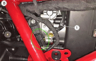
TABLE B1 - FILTER BOX AND THROTTLE BODY CONNECTIONS
- Fastener clip
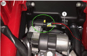
TABLE B2 - FILTER BOX AND THROTTLE BODY CONNECTIONS
- Pull the following cable to the outside of the frame
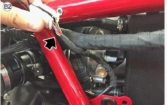
TABLE B3 - FILTER BOX AND THROTTLE BODY CONNECTIONS
- Pull the following cable to the outside of the frame
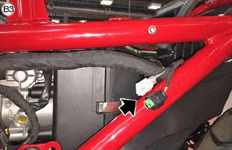
TABLE C - SIDE STAND SWITCH AND CORRECT ASSEMBLY ON THE VEHICLE
- Overall view of pre-assembly
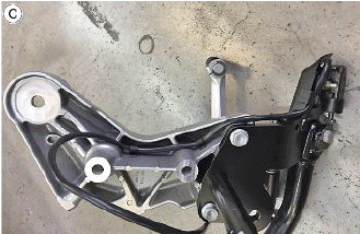
TABLE C1 - SIDE STAND SWITCH AND CORRECT ASSEMBLY ON THE VEHICLE
- Fastener clip
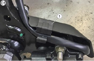
TABLE C2 - SIDE STAND SWITCH AND CORRECT ASSEMBLY ON THE VEHICLE
- Clip
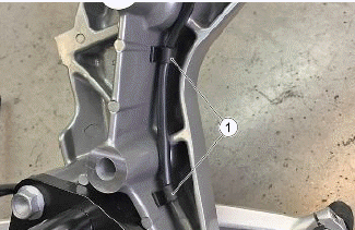
TABLE C3 - SIDE STAND SWITCH AND CORRECT ASSEMBLY ON THE VEHICLE
- Fastener clip
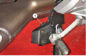
TABLE C4 - SIDE STAND SWITCH AND CORRECT ASSEMBLY ON THE VEHICLE
- Side stand cabling
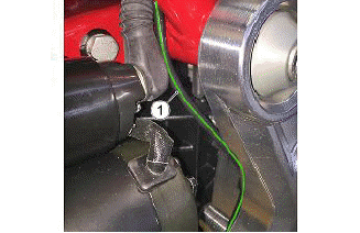
TABLE C5 - SIDE STAND SWITCH AND CORRECT ASSEMBLY ON THE VEHICLE
- Side stand cabling
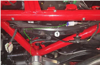
TABLE C6 - SIDE STAND SWITCH AND CORRECT ASSEMBLY ON THE VEHICLE
- Proceed as indicated in the figure
Fasten the side support on the frame (upper part)
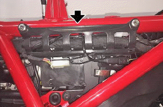
TABLE C6 - SIDE STAND SWITCH AND CORRECT ASSEMBLY ON THE VEHICLE
- Proceed as indicated in the figure
Fasten the side support on the frame (upper part)
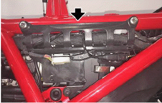
TABLE D - BRAKE LIGHT SWITCH AND CORRECT ASSEMBLY ON THE VEHICLE
- Overall view
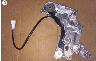
TABLE D1 - BRAKE LIGHT SWITCH AND CORRECT ASSEMBLY ON THE VEHICLE
- Brake light switch support
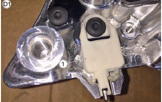
TABLE D2 - BRAKE LIGHT SWITCH AND CORRECT ASSEMBLY ON THE VEHICLE
- Gearbox in neutral switch connection (mounted on support)
- Brake light switch

TABLE D3 - BRAKE LIGHT SWITCH AND CORRECT ASSEMBLY ON THE VEHICLE
- Support for AMP connection
- Small clamp
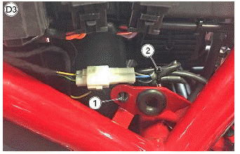
TABLE E - HIGH VOLTAGE CABLES
- Left cylinder H.V. cable
H.V. cable route
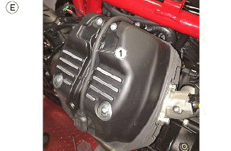
TABLE E1 - HIGH VOLTAGE CABLES
- Left cylinder cable guide
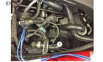
TABLE E2 - HIGH VOLTAGE CABLES
- Left cylinder coil connector
H.V. cable route to the left cylinder coil
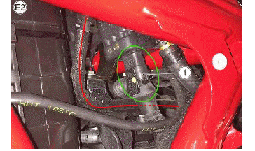
TABLE E3 - HIGH VOLTAGE CABLES
- Right cylinder H.V. cable
H.V. cable route
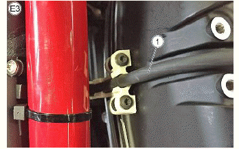
TABLE E4 - HIGH VOLTAGE CABLES
- Right cylinder cable guide
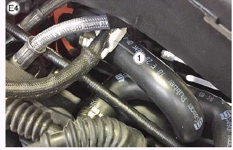
TABLE E5 - HIGH VOLTAGE CABLES
- Proceed as indicated in the figure
Overall view of how the two H.V. cables look with the respective cable guides indicated in the figure
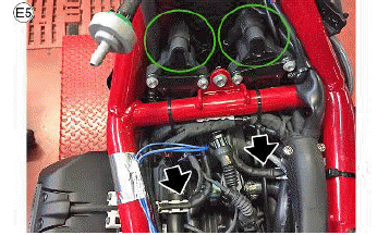
TABLE E6 - HIGH VOLTAGE CABLES
- H.V. cables
The two H.V. cables must be fastened under the specific clips located in the ABS modulator support
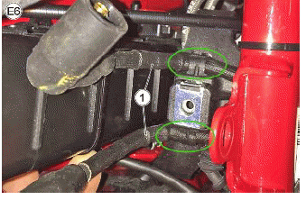
TABLE E7 - HIGH VOLTAGE CABLES
- Coils
View of completed coils assembly
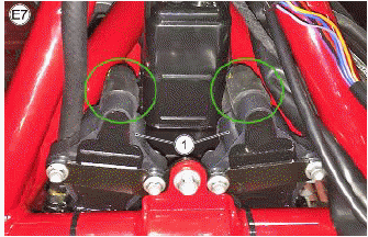
TABLE F - ABS
- ABS control unit connector
Does not require dust boot. For correct connection, see "installation of the ABS modulator"
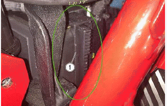
FIGURE G - STARTER MOTOR
- Start relay cable
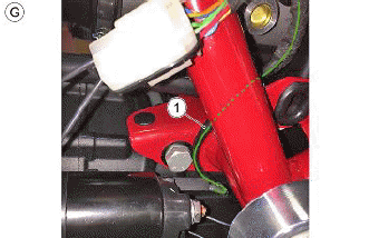
FIGURE G1 - STARTER MOTOR
- Power cable
Fasten the power cable to the clamp with nut and washer and cover everything with the specific black cap
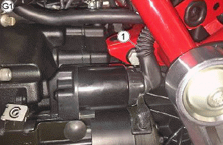
FIGURE G2 - STARTER MOTOR
- Power cable
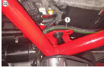
FIGURE G3 - STARTER MOTOR
- Proceed as indicated in the figure
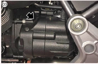
TABLE H - EARTH POINT ON ENGINE
- Earth cable
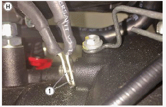
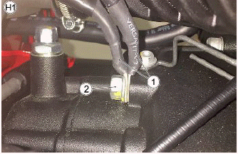
TABLE H1 - EARTH POINT ON ENGINE
- Earth cable
- Nut
Fasten everything as illustrated in the figure
See also:
 Moto Guzzi V85 TT - Service manual > Front side
TABLE A - VOLTAGE REGULATOR ASSEMBLY Regulator side flywheel cable Regulator cable to wiring harness
Moto Guzzi V85 TT - Service manual > Back side
TABLE A - WIRING ON THE SEAT PILLAR Medium sized cable ties Once the lower seat pillar closing is mounted, remove the two clamps (1)
 Ducati Scrambler
 Fantic Caballero 500
 Indian FTR 1200
 Moto Guzzi V85 TT
 Royal Enfield Bullet Trials Works Replica
 Triumph Scrambler 1200 XE
 Triumph Street Scrambler
 Yamaha XSR700
 Ducati Scrambler 800
 Moto Guzzi V85 TT
 Triumph Scrambler 1200 XC