 Triumph Scrambler 1200 XC - Service manual > Front Suspension
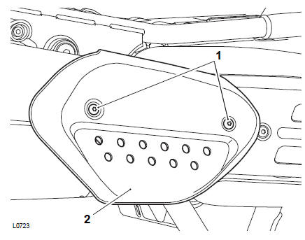
1. Fit the sensor to the airbox and tighten thefixing to 1.5 Nm.
2. Reconnect the electrical connector to the sensor.
Perform the following operations:
- Refit the right hand Side Panels
- Battery - Installation
- Seat - Installation
Perform the following operations:
- Seat - Removal
- Battery - Removal
- Fuel Tank - Removal
- Coolant Replacement - Drainage
- Radiator - Removal
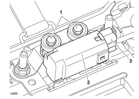
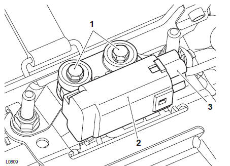
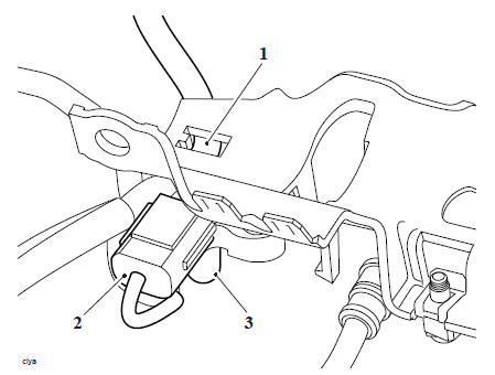
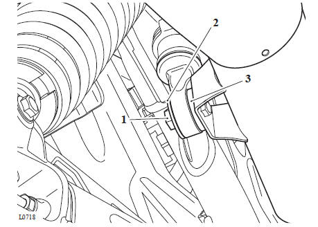
1. Detach the coolant temperature connector from the ignition coils bracket.
- Coolant temperature sensor connector
- Ignition coils bracket
2. Press the wire locking device fully in and detach the coolant temperature sensor from the main harness.
Note
Note the routing of the coolant temperature harness for installation.
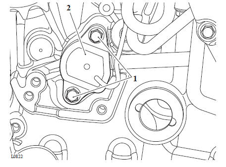
3. Remove the rubber cover and using a suitable 19 mm slotted socket, remove the coolant temperature sensor from the cylinder head and discard the washer.
- Coolant temperature sensor
1. Fit a new washer to the coolant temperature sensor.
2. Apply ThreeBond 1374 to the threads of the coolant temperature sensor.
3. Fit the coolant temperature sensor into the cylinder head and tighten to 18 Nm.
4. Route the wiring as noted prior to removal and reconnect the sensor to the main harness.
5. Refit the coolant temperature sensor electrical connector to the ignition coils bracket.
Perform the following operations:
- Radiator - Installation
- Coolant Replacement - Filling
- Fuel Tank - Installation
- Battery - Installation
- Seat - Installation
WARNING
Before starting work, ensure the motorcycle is stabilised and adequately supported. This will help prevent it from falling and causing injury to the operator or damage to the motorcycle.
Perform the following operations:
- Seat - Removal
- Battery - Removal
- Fuel Tank - Removal
- Ignition Coils - Removal
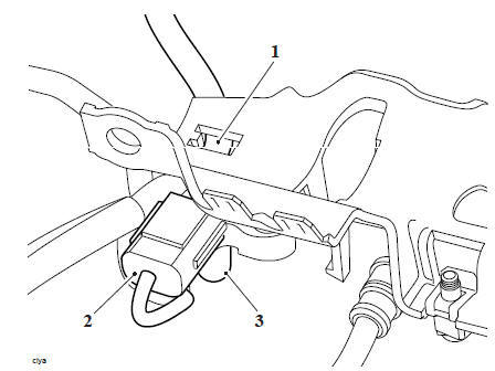
1. Remove the fixing and remove the MAP sensor.

- MAP sensor
- Fixing
1. Fit the sensor to the ignition coils bracket and tighten the fixing to 2 Nm.
Perform the following operations:
- Ignition Coils - Installation
- Fuel Tank - Installation
- Battery - Installation
- Seat - Installation
WARNING
Before starting work, ensure the motorcycle is stabilised and adequately supported. This will help prevent it from falling and causing injury to the operator or damage to the motorcycle.
Perform the following operations:
- Seat - Removal
- Battery - Removal
- Throttle Body and Inlet Manifold Assembly - Removal
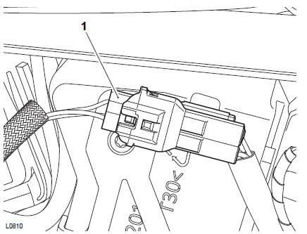
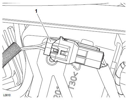
1. Disconnect the electrical connector from the sensor.
2. Release the fixing and remove the sensor.
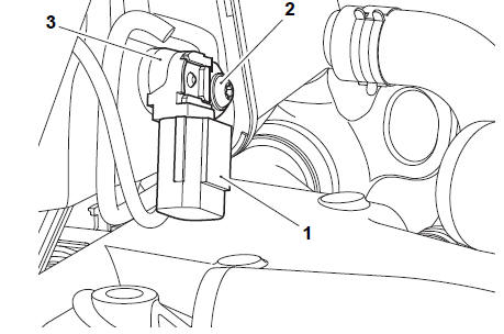
- Electrical connector
- Fixing
- Ambient air pressure sensor
1. Fit the sensor to the airbox and secure with the fixing. Tighten to 2 Nm.
2. Reconnect the electrical connector to the sensor.
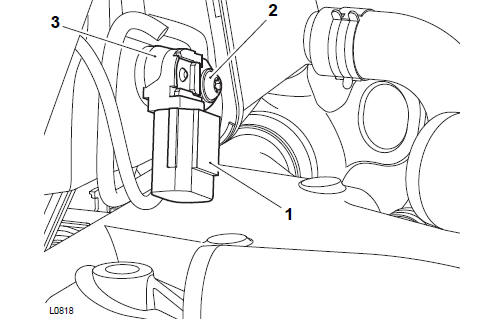
- Electrical connector
- Fixing
- Ambient air pressure sensor
Perform the following operations:
- Throttle Body and Inlet Manifold Assembly - Installation
- Battery - Installation
- Seat - Installation
WARNING
Before starting work, ensure the motorcycle is stabilised and adequately supported. This will help prevent it from falling and causing injury to the operator or damage to the motorcycle.
Perform the following operations:
- Seat - Removal
- Battery - Removal
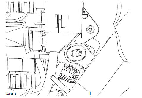
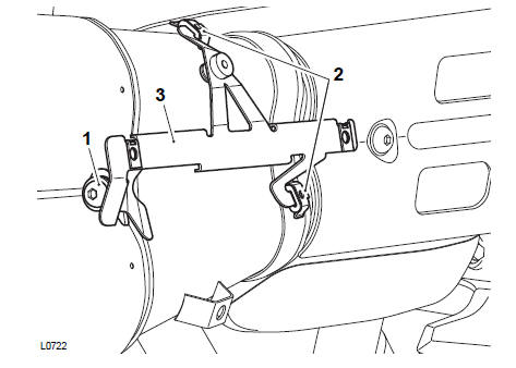
1. Remove and discard the fixings securing the fall detection switch to the frame below the storage box.
2. Disconnect the electrical connector and remove the falldetection switch.
- Fixings
- Fall detection switch
- Electrical connector
1. Connect the electrical connector to the fall detection switch.
2. Fit the fall detection switch to the frame below storeage box and tighten the new fixings to 3 Nm.
- Fixings
- Fall detection switch
- Electrical connector
Perform the following operations:
- Battery - Installation
- Seat - Installation
WARNING
Before starting work, ensure the motorcycle is stabilised and adequately supported. This will help prevent it from falling and causing injury to the operator or damage to the motorcycle.
Perform the following operations:
- Seat - Removal
- Battery - Removal
- Right hand Side Panels
- Front Sprocket Cover - Removal
1. On the right side of the airbox, disconnect the gear position sensor electrical connector from the main harness.
- Gear position sensor electrical connector
Note
Note the routing of the gear position sensor harness for installation.
2. Route the gear position sensor harness through the frame to the harness guide on the crankcase.
Note
Note that the white tape on the harnesses within the harness guide aligns with the upper gap for installation.
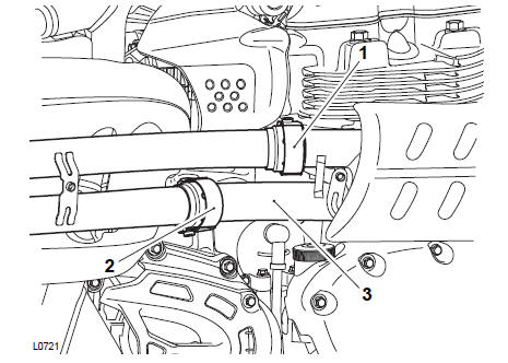
3. Remove and discard the fixings and detach the harness guide from the crankcase.
- Fixings
- Harness guide
- Upper gap
- White tape
4. Carefully remove the gear position sensor harness from the harness guide.
- Harness guide
- Harness
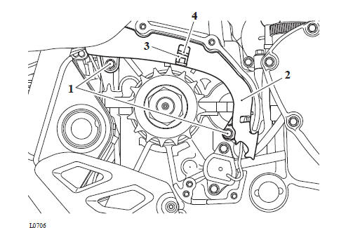
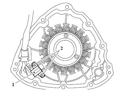
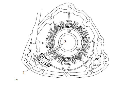
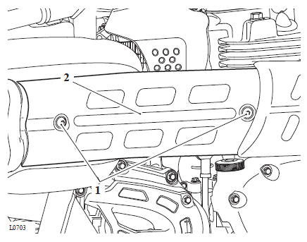
5. Remove and discard the two fixings and remove the gear position sensor.
- Fixings
- Gear position sensor
WARNING
Before starting work, ensure the motorcycle is stabilised and adequately supported. This will help prevent it from falling and causing injury to the operator or damage to the motorcycle.
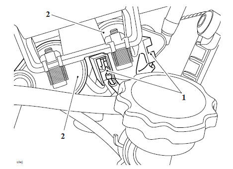
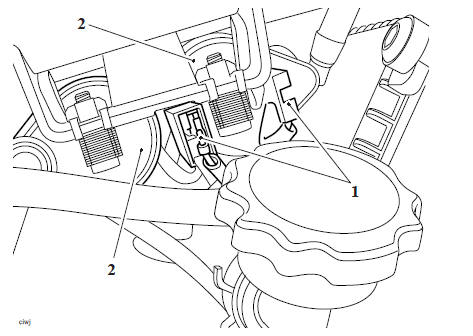
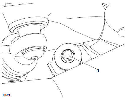
1. Fit new O-rings to the sensor. Lubricate the O-rings with a smear of petroleum jelly.
2. Position the sensor to the engine, ensuring that the lug on the sensor engages with the slot in the selector drum shaft.
- Slot
- Lug
- Gear position sensor
3. Secure with the two new fixings and tighten to 5 Nm.
4. Carefully fit the gear position sensor harness into the harness guide as noted for removal with the white tape shown in the upper gap.
5. Secure the harness guide to the crankcase and tighten the new fixings to 4 Nm.
- Fixings
- Harness guide
- Upper gap
- White tape
6. Route the gear position sensor harness through the frame to the right hand side of the airbox, as noted for removal. Connect the gear position sensor electrical connector to the main harness.
- Gear position sensor 1. electrical connector
7. Reset the neutral position adaption (see Neutral Position Adaption).
Perform the following operations:
- Front Sprocket Cover - Installation
- Right hand Side Panels
- Battery - Installation
- Seat - Installation
WARNING
Before starting work, ensure the motorcycle is stabilised and adequately supported. This will help prevent it from falling and causing injury to the operator or damage to the motorcycle.
- Disconnect the high tension cables from the spark plugs.
Note
- The ignition coil wires identified with the red tape are fitted to the right hand side of the ignition coils.
- Note the position of the four wires connected to the ignition coils for installation.
2. Disconnect the four wires from the ignition coils (two either side of the ignition coils).
- Ignition coil connections (right hand side shown)
- Ignition coils
3. Detach the coolant temperature connector from the ignition coils bracket.
- Coolant temperature sensor connector
4. Remove the three fixings and detach the ignition coil bracket from the motorcycle frame.
- Fixing (right hand side shown)
- Ignition coil bracket
Note
Note the routing of the fuel pump harness on the ignition coil bracket for installation.
5. Detach the fuel pump harness from the ignition coils bracket.
6. Disconnect the MAP sensor hose and the electrical connector from the MAP sensor.
- Fuel pump harness
- MAP sensor electrical connector
- MAP sensor hose
Note
The front ignition coil has the longer HT lead.
7. Remove and discard the four fixings and remove the ignition coils from their bracket.
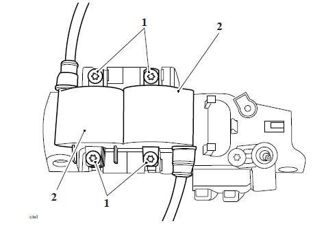
- Fixings
- Ignition coils
WARNING
Before starting work, ensure the motorcycle is stabilised and adequately supported. This will help prevent it from falling and causing injury to the operator or damage to the motorcycle.
1. Position the ignition coils onto their bracket, secure with new fixings and tighten to 3 Nm.
2. Connect the MAP sensor hose and the electrical connector to the MAP sensor.
3. Attach the fuel pump harness to the ignition coil bracket, as noted for removal.
- Fuel pump harness
- MAP sensor electrical connector
- MAP sensor hose
4. Position the ignition coils and bracket assembly to the motorcycle frame, secure with the fixings and tighten to 3 Nm.
5. Attach the coolant temperature sensor connector onto the ignition coil bracket.
Note
The wires for the right hand side of the ignition coils are identified with the red tape.
6. Connect the four wires from the ignition coils as noted for removal (two either side of the ignition coils).
- Ignition coil connections (right hand side shown)
- Ignition coils
7. Connect the high tension cables to the spark plugs.
Perform the following operations:
- Fuel Tank - Installation
- Battery - Installation
- Seat - Installation
WARNING
Before starting work, ensure the motorcycle is stabilised and adequately supported. This will help prevent it from falling and causing injury to the operator or damage to the motorcycle.
Perform the following operations:
- Exhaust Silencer - Removal
- Side Panels
- Rear Mudguard - Removal
- Engine Electronic Control Module (ECM) - Removal
Note
Before the disconnection of any wiring, note the routing of all wiring and wiring connectors on both sides of the airbox.
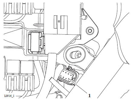
1. Disconnect the electrical connector from the keyless electronic control module (ECM).
- Keyless ECM electrical connector
2. Remove the rear grommet for the left hand side panel for access to battery box lower fixing.
- Grommet
- Fixings
- Battery box
3. Detach the starter motor solenoid from the right hand side of the battery box.
Note
- The keyless ECM is attached to the underside of the battery box.
4. Remove the two fixings securing the battery box to the frame and carefully manoeuvre the battery box rearward for removal.
- Starter motor solenoid
- Fixing
- Battery box
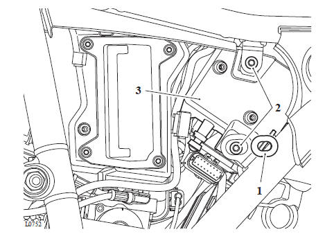
5. Release the fixing and remove the keyless ECM.
- Fixings
- Keyless ECM
WARNING
Before starting work, ensure the motorcycle is stabilised and adequately supported. This will help prevent it from falling and causing injury to the operator or damage to the motorcycle.
1. Fit the keyless ECM to the battery box as noted for and tighten the fixings to 3 Nm.
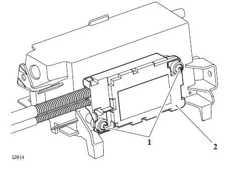
- Fixings
- Keyless ECM
2. Position the battery box to the rear of the airbox and connect the electrical connector to the keyless ECM.
- Keyless ECM electrical connector
3. Carefully position the battery box to the rear of the airbox and secure to the frame.
Tighten the fixings to 6 Nm.
4. Attach the starter motor solenoid to the right hand side of the battery box.
- Starter motor solenoid
- Fixing
- Battery box
5. Fit the rear grommet for the left hand side panel.
6. If a replacement keyless ECM has been fitted, it must be setup as described in Setup Flow Chart - Replacement Keys and Keyless ECM.
WARNING
Before starting work, ensure the motorcycle is stabilised and adequately supported. This will help prevent it from falling and causing injury to the operator or damage to the motorcycle.
Note
If the crankshaft position sensor needs to be replaced, the alternator stator will also be replaced as they are one assembly.
Perform the following operations:
- Seat - Removal
- Battery - Removal
- Alternator Cover - Removal
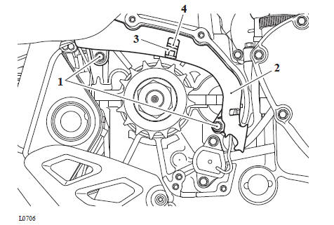
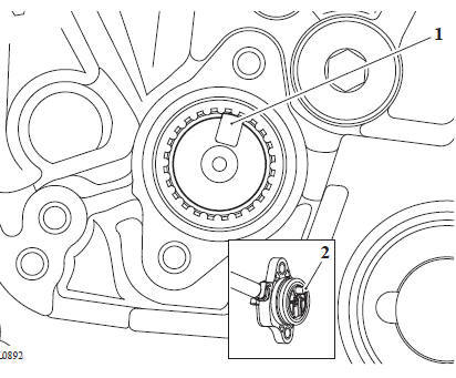
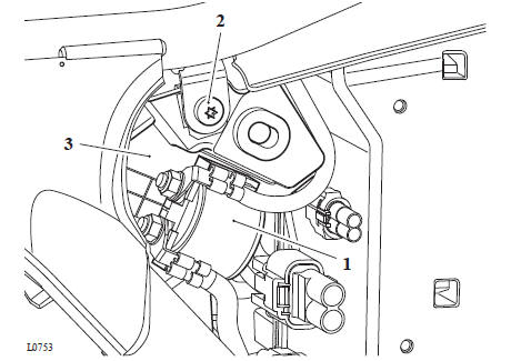
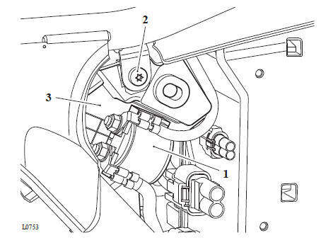
1. Remove and discard the fixings securing the crankshaft position sensor to the alternator cover.
- Crankshaft position sensor
- Fixings
Note
Note the routing of the alternator harness for installation.
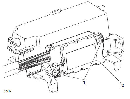
2. Remove and discard the fixing and remove the harness cover from the alternator cover.
3. Remove and discard the fixings securing the stator to the alternator cover and remove the stator.
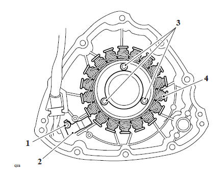
- Fixing
- Harness cover
- Fixings
- Stator
WARNING
Before starting work, ensure the motorcycle is stabilised and adequately supported. This will help prevent it from falling and causing injury to the operator or damage to the motorcycle.
1. Position the stator to the alternator cover and route the harness as noted for removal. Secure the stator with new fixings and tighten to 12 Nm.
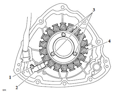
- Fixing
- Harness cover
- Fixings
- Stator
2. Fit the harness cover and tighten the new fixing to 6 Nm.
Note
The air gap for the crankshaft position sensor is not adjustable.
3. Fit the crankshaft position sensor with two new fixings and tighten to 6 Nm.
- Crankshaft position sensor
- Fixings
Perform the following operations:
- Alternator Cover - Installation
- Battery - Installation
- Seat - Installation
WARNING
Before starting work, ensure the motorcycle is stabilised and adequately supported. This will help prevent it from falling and causing injury to the operator or damage to the motorcycle.
WARNING
If the engine has recently been running, the exhaust components may be hot to the touch. Contact with the hot components may cause damage to exposed skin.
To avoid skin damage, always allow the hot parts to cool before working on the exhaust system.
Perform the following operations:
- Seat - Removal
1. Release the two fixings and remove the silencer rear heat shield.
- Fixings
- Heat shield
2. Remove the fixing and move the heat shield bracket rearwards for removal.
Collect the two rubber grommets.
- Fixing
- Rubber grommets
- Heat shield bracket
3. Release the fixings and remove the centre heat shield.
- Fixings
- Centre heat shield
Note
Always note the position and orientation of the exhaust clamps prior to releasing them, and return them to the noted position and orientation on assembly.
4. Release the clamps securing the silencers to the catalytic converter
- Upper silencer clamp
- Lower silencer clamp
- Catalytic converter
Note
Note the position of the shouldered washers and rubber bushes in the silencer mountings for installation.
5. Support the silencer assembly and remove the upper fixing.
- Fixing
Note
The lower mounting consists of two rubber bushes, one shouldered washer and a bolt. Note the position of the shouldered washer for installation.
6. Release the lower mounting fixing and remove the exhaust silencer assembly.
Collect the rubber bushes and the shouldered washer.
- Fixing
- Shouldered washer
- Rubber bushes
7. Remove and discard the exhaust gaskets.
See also:
 Triumph Scrambler 1200 XC - Service manual > Removal and Installation - Engine Management Components
WARNING Observe the warning advice given in the General Information section on the safe handling of fuel and fuel containers. A fire, causing personal injury and damage to property could result from spilled fuel or fuel not handled or stored correctly.
 Ducati Scrambler
 Fantic Caballero 500
 Indian FTR 1200
 Moto Guzzi V85 TT
 Royal Enfield Bullet Trials Works Replica
 Triumph Scrambler 1200 XE
 Triumph Street Scrambler
 Yamaha XSR700
 Ducati Scrambler 800
 Moto Guzzi V85 TT
 Triumph Scrambler 1200 XC