 Triumph Scrambler 1200 XC - Service manual > Removal and Installation - Engine Management Components
WARNING
Observe the warning advice given in the General Information section on the safe handling of fuel and fuel containers.
A fire, causing personal injury and damage to property could result from spilled fuel or fuel not handled or stored correctly.
Perform the following operations:
- Seat - Removal
- Battery - Removal
WARNING
Never drain fuel from the tank using non-approved, non-professional standard fuel handling equipment. A fire causing destruction of property and injury to persons may result from use of non-approved fuel handling equipment.
1.Using proprietary professional automotive workshop equipment approved for fuel handling, drain all fuel from the fuel tank.
2. Remove the fuel tank (see Fuel Tank - Removal).
3. Invert the fuel tank and place on a protective surface to prevent paint damage.
4. Remove the ring of fixings securing the fuel pump mounting plate to the tank.
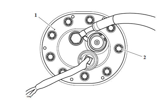
- Fuel pump mounting plate
- Fixing
5. Detach the pump assembly from the fuel tank.
6. Disconnect the fuel level sensor from the fuel pump assembly harness.
- Fuel level sensor connector
7. Remove the fuel pump assembly and discard the fuel pump plate seal.
1. Inspect all hoses for cracks, splits, fraying and other damage. Replace as necessary.
2. Check all hose clamps for cracks and signs of distortion. Replace as necessary.
3. Check the mesh filter for damage and replace the fuel pump if necessary.
WARNING
Observe the warning advice given in the General Information section on the safe handling of fuel and fuel containers.
A fire, causing personal injury and damage to property could result from spilled fuel or fuel not handled or stored correctly.
1. Position a new fuel pump plate seal to the fuel pump plate as noted for removal.
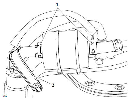
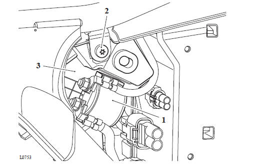
2. Route the fuel level sensor harness under the baffle hose and fuel pump assembly harness, as shown in the illustration below, and connect to the fuel pump assembly harness.
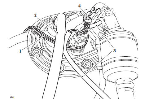
- Fuel level sensor harness
- Baffle hose
- Fuel pump harness
- Fuel level sensor connector
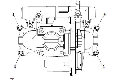
3. Refit the fuel pump assembly to the fuel tank. Fit and tighten the fixings to 5 Nm in the sequence shown below.
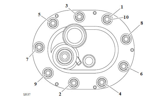
Fuel Pump Plate Tightening Sequence
4. Refit the fuel tank (see Fuel Tank - Installation).
5. Refill the fuel tank with the fuel drained during removal, and check carefully for fuel leaks.
Perform the following operations:
- Battery - Installation
- Seat - Installation
Perform the following operations:
- Fuel Pump Assembly - Removal
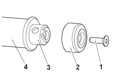
1. Remove and discard the circlip securing the fuel pressure regulator in its housing
- Circlip
- Fuel pressure regulator
2. Remove the fuel pressure regulator from the fuel pump plate. Discard the large O-ring from the fuel pressure regulator and the small O-ring in the pressure regulator housing.
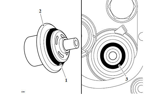
- Large O-ring
- Fuel pressure regulator
- Small O-ring
1.Inspect all hoses for cracks, splits, fraying and other damage. Replace as necessary.
2. Check all hose clamps for cracks and signs of distortion. Replace as necessary.
3. Check the mesh filter for damage and replace the fuel pump if necessary.
1. Install new O-rings to the fuel pressure regulator.
- O-rings
2. Apply a small amount of grease, conforming to NLGI 2 specification, to the two O-rings.
3. Position the fuel pressure regulator squarley to the fuel pump plate and press it evenly into its housing.
4. Secure the fuel pressure regulator with a new circlip.
5. Refit the hose and secure with the hose clip. Check for any fuel leaks and rectify if necessary.
Perform the following operations:
- Fuel Pump Assembly - Installation
Perform the following operations:
- Fuel Pump Assembly - Removal
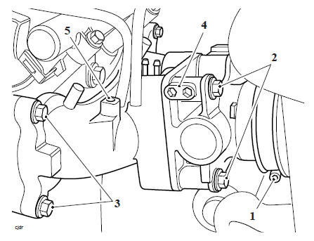
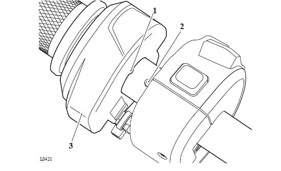
1. Release the fuel hose clip from the fuel pump side of the fuel filter.
2. Remove the hose bracket from the fuel pump bracket.
- Hose clips
- Hose bracket
3. Release the hose clip securing the baffle housing to the fuel pump.
4. Reposition the hose clip and carefully slide the baffle housing off the fuel pump body.
Note
- Note the orientation of the baffle housing for installation.
- It is not necessary to disconnect the baffle housing hose from the fuel pressure regulator unless it is to be removed at the same time as the fuel pump.
- Baffle housing
- Hose clip
5. Remove the baffle housing hose clip over the inlet filter.
6. Disconnect the fuel pump electrical connector.
7. Remove the fuel pump securing bolt and strap.
- Strap
- Bolt
8. Detach the fuel pump and connector hose from the fuel pump bracket as an assembly.
9. If necessary, release the hose clip and remove the connector hose from the pump.
1. Inspect all hoses for cracks, splits, fraying and other damage. Replace as necessary.
2. Check all hose clamps for cracks and signs of distortion. Replace as necessary.
3. Check the mesh filter for damage and replace the fuel pump if necessary.
1. If removed, refit the connector hose to the fuel pump. Secure with the hose clip.
2. Position the fuel pump to the bracket, ensuring the feet of the rubber isolator engage correctly in the fork.
- Fork
- Isolator feet
3. Align the fuel pump to the fuel pump bracket and fit the connector hose on to the fuel filter.
4. Fit the fuel pump strap, secure with a new bolt and 4. tighten to 4 Nm.
- Strap
- Bolt
5. Reconnect the fuel pump electrical connector.
6. Position the baffle housing hose clip loosely over the fuel pump body.
7.Check that the baffle material within the baffle housing is positioned as noted for removal.
8. Refit the baffle housing over the fuel pump, as noted for removal. Refit the hose clip and tighten to 3 Nm.
Perform the following operations:
- Fuel Pump Assembly - Installation
WARNING
Observe the warning advice given in the General Information section on the safe handling of fuel and fuel containers.
A fire, causing personal injury and damage to property could result from spilled fuel or fuel not handled or stored correctly.
Note
- The fuel level sensor is located inside the fuel tank on the right hand side.
- Access to the fuel level sensor is through the aperture for the fuel pump.
Perform the following operations:
- Fuel Pump Assembly - Removal
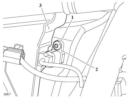
Note
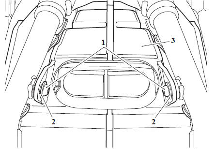
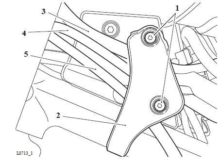
The mounting for the fuel level sensor is located inside the fuel tank. The illustration shows the bracket outside the fuel tank for clarity.
- Release the locking device and slide the fuel level sensor up the bracket and release the two locating lugs from the bracket.
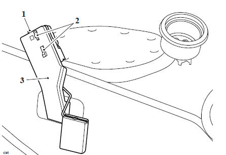
- Locking device
- Locating lugs
- Bracket
2. Remove the fuel level sensor.
WARNING
Observe the warning advice given in the General Information section on the safe handling of fuel and fuel containers.
A fire, causing personal injury and damage to property could result from spilled fuel or fuel not handled or stored correctly.
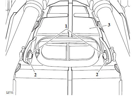
1. Align the two locating lugs into the holes in the bracket.
2. Slide the fuel level sensor down the bracket for the locking device to engage and secure the sensor.
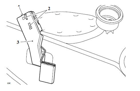
- Locking device
- Locating lugs
- Bracket
Perform the following operations:
- Fuel Pump Assembly - Installation
- Refit the fuel tank (see Fuel Tank - Installation).
WARNING
Before starting work, ensure the motorcycle is stabilised and adequately supported. This will help prevent it from falling and causing injury to the operator or damage to the motorcycle.
Perform the following operations:
- Seat - Removal
- Battery - Removal
- Fuel Tank - Removal
- Exhaust Silencer - Removal
- Side Panels
- Rear Mudguard - Removal
- Engine Electronic Control Module (ECM) - Removal
Note
Before the disconnection of any wiring, note the routing of all wiring and wiring connectors on both sides of the airbox.
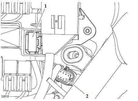
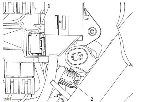
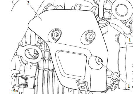
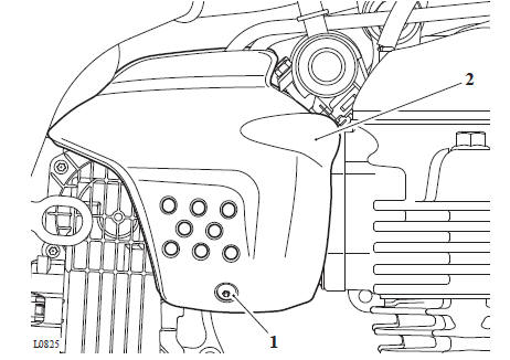
1. Release the fixing and detach the air temperature sensor from the airbox.
2. Disconnect the ambient air pressure sensor connector.
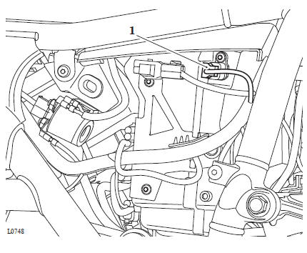
1. Air temperature sensor
2. Ambient air pressure sensor
3. Cut the cable tie and detach the connector bracket.
4. Remove the fixings and detach the connector bracket from the right hand side of the airbox.
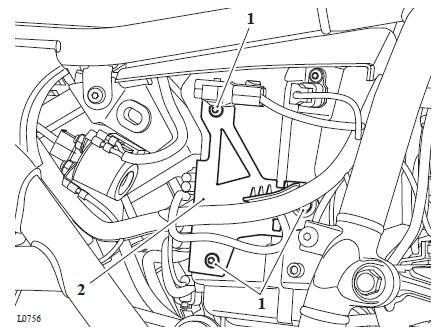
- Fixings
- Connector bracket
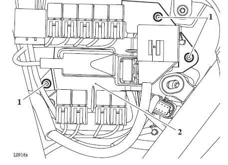
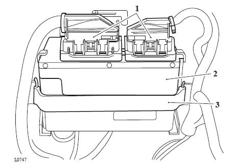
5. Detach the main fuse from the relay bracket.
6. Disconnect the electrical connector from the keyless electronic control module (ECM).
- Main fuse
- Keyless ECM electrical connector
7. Remove the fixings and detach the relay bracket from the left hand side of the airbox.
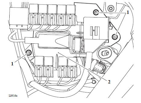
- Fixings
- Relay bracket
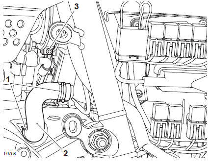
8. Release the two hose clips and remove the engine breather hose.
9. Loosen the clamp for the throttle body intake hose.
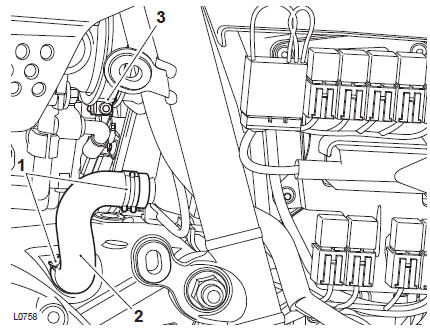
- Clips
- Engine breather pipe
- Clamp
10. Remove the rear grommet for the left hand side panel for access to battery box lower fixing.
11. Remove the two fixings securing the battery box to the frame.
- Grommet
- Fixings
- Battery box
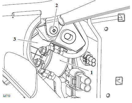
12. Detach the starter motor solenoid from the right hand side of the battery box.
Note
The keyless ECM is attached to the underside of the battery box.
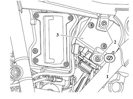
13. Release the fixing and carefully manoeuvre the battery box rearward for removal.
- Starter motor solenoid
- Fixing
- Battery box
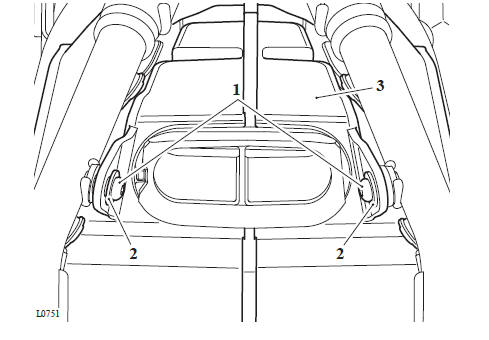
14. Remove the fixing and shouldered washer from both sides of the airbox
- Fixing
- Shouldered washer
- Airbox
Note
When removing the airbox, ensure that the brake lines on the right hand side of the frame do not get damaged.
15. Manoeuvre the airbox rearward to remove it from the motorcycle.
WARNING
Before starting work, ensure the motorcycle is stabilised and adequately supported. This will help prevent it from falling and causing injury to the operator or damage to the motorcycle.
Note
When installing the airbox, ensure that the brake lines on the right hand side of the frame do not get damaged.
1. Position the airbox to the frame ensuring the throttle body air duct is correctly aligned to the throttle body.
2. Check that the harnesses and hoses are routed as noted on removal.
3. Tighten the intake hose clamp to 1.5 Nm.
4. Fit the fixing and shouldered washer to both sides of the airbox, do not fully tighten at this stage.
- Fixing
- Shouldered washer
- Airbox
5. Attach the main fuse to the relay bracket.
Note
The keyless ECM is attached to the underside of the battery box.
6. Position the battery box to the rear of the airbox and connect the electrical connector to the keyless electronic control module (ECM).
- Main fuse
- Keyless ECM electrical connector
7. Attach the relay bracket to the left hand side of the airbox, ensuring the harness is not trapped, and tighten the three fixings to 1.5 Nm.
- Fixings
- Relay bracket
8. Carefully position the battery box to the rear of the airbox and secure to the frame.
Tighten the fixings to 6 Nm.
9. Tighten the airbox fixings to 6 Nm.
- Fixing
- Airbox
10. Attach the starter motor solenoid to the right hand side of the battery box.
- Starter motor solenoid
- Fixing
- Battery box
11. Fit the rear grommet for the left hand side panel.
12. Refit the engine breather hose and secure with the hose clips.
- Clips
- Engine breather pipe
13. Attach the connector bracket to the right hand side of the airbox and tighten the fixings to 1.5 Nm.
- Fixings
- Connector bracket
14. Attach the air temperature sensor to the airbox and tighten its fixing to 1.5 Nm.
15. Connect the ambient air pressure sensor connector.
- Ambient air temperature sensor
- Air pressure sensor
Perform the following operations:
- Engine Electronic Control Module (ECM) - Installation
- Rear Mudguard - Installation
- Side Panels
- Fuel Tank - Installation
- Battery - Installation
- Seat - Installation
WARNING
Before starting work, ensure the motorcycle is stabilised and adequately supported. This will help prevent it from falling and causing injury to the operator or damage to the motorcycle.
Perform the following operations:
- Seat - Removal
- Battery - Removal
- Exhaust Silencer - Removal
- Side Panels
1. Remove the fixing and remove the air intake finishers.
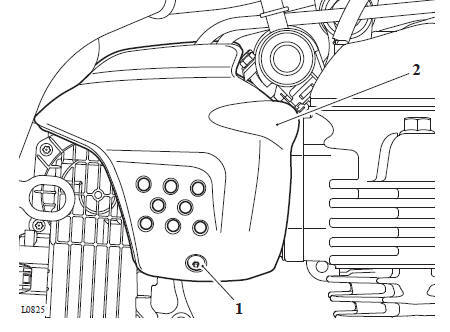
- Fixing
- Air intake finisher (right hand side shown)
Note
For the USA and Canadian Markets only, there is an ignition master switch and bracket assembly secured to the left hand side of the throttle body by the finisher mounting and its fixings.
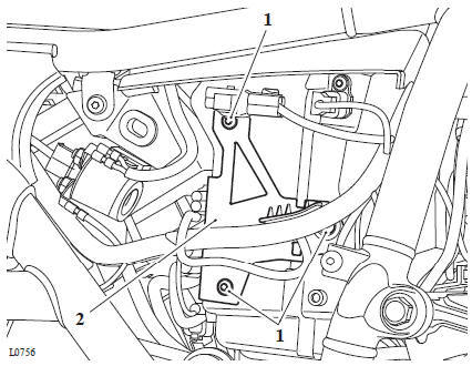
2. Remove the two fixings and remove the mountings for the air intake finisher.
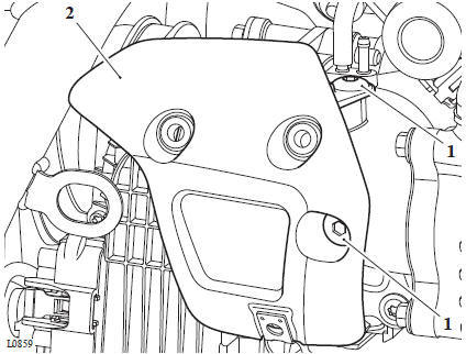
- Fixings
- Mounting (right hand side shown)
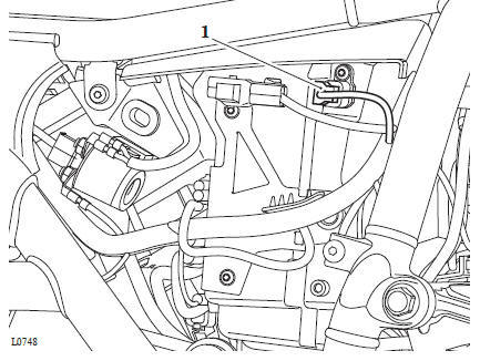
3. Disconnect the throttle actuator motor multiplug.
- Multiplug
- Throttle actuator motor
Note
Note which spigot on the inlet manifold the MAP sensor hose is fitted to and, if fitted, which spigot the evaporative emissions hose is fitted to for installation.
4. Disconnect the MAP hose and the evaporative emissions hose from the inlet manifold.
- Evaporative hose
- MAP sensor hose
5. Loosen the throttle body hose clamp.
6. Remove the four fixings securing the throttle body to the inlet manifold.
7. Remove the four fixings securing the inlet manifold to the cylinder head and remove the inlet manifold.
8. Remove the throttle body
- Clamp
- Throttle body fixings (left hand side)
- Inlet manifold fixings (left hand side)
- Throttle body
- Inlet manifold
Note
Note the orientation of the throttle body for installation.
9. Remove and discard the three seals on the inlet manifold.
- Inlet manifold
- Seals
Intake Air Temperature Sensor - Installation
Coolant Temperature Sensor - Removal
Coolant Temperature Sensor - Installation
WARNING
Before starting work, ensure the motorcycle is stabilised and adequately supported. This will help prevent it from falling and causing injury to the operator or damage to the motorcycle.
CAUTION
From VIN 783907 the purge valve restrictor has been removed from the purge valve hose. The restriction is now controlled by the purge valve spigot on the inlet manifold.
Fitting a new manifold with the purge valve restrictor in the spigot and using the original hose with a restrictor in it will not allow the carbon cannister to purge correctly.
Failure to purge the carbon cannister correctly will cause irreparable damage to the carbon cannister.
Note
- If replacing the inlet manifold on models up to VIN 783906 check the purge control valve hose for the restrictor, approximately 25 mm from the inlet manifold end of the hose.
- If the hose has the restrictor, replace the hose with a new hose without the restrictor. Restriction is controlled by the spigot pressed into the new inlet manifold.
- When ordering replacement parts, always refer to the EPC.
1. Ensure the mating surfaces on the inlet manifold and the cylinder head are clean.
2. Fit three new seals to the mating surfaces of the inlet manifold.
- Inlet manifold
- Seals
3. Fit the inlet manifold to the cylinder head. Do not fully tighten the fixings at this stage.
4. Ensure the mating surfaces of the throttle body and inlet manifold are clean.
5. Position the throttle body to the throttle body hose. Do not tighten the clamp at this stage.
6. Fit the throttle body to the inlet manifold. Do not fully tighten the fixings at this stage.
7. Tighten the inlet manifold to cylinder head fixings to 9 Nm in the sequence shown below.
8. Retighten the fixings one 8. and two to 9 Nm.
Tightening Sequence
9. Tighten the throttle body to inlet manifold fixings to 9 Nm.
10. Ensure the throttle body hose is correctly fitted and tighten the clip to 1.5 Nm.
- Clamp
- Throttle body fixings (left hand side)
- Inlet manifold fixings (left hand side)
- Throttle body
- Inlet manifold
11. Connect the multiplug to the throttle actuator motor.
12. Connect the MAP hose and the evaporative emissions hose (if fitted) to the inlet manifold, as noted for removal.
Note
For the USA and Canadian Markets only, there is an ignition master switch and bracket assembly secured to the left hand side of the throttle body by the finisher mounting and its fixings.
13. Fit the mountings for the air intake finisher and tighten its new fixings to 3 Nm.
- Fixings
- Mounting (right hand side shown)
14. Fit the air intake finishers and tighten the new fixing to 1.5 Nm.
- Fixing
- Air intake finisher (right hand side shown)
Perform the following operations:
- Side Panels
- Exhaust Silencer - Installation
- Fuel Tank - Installation
- Battery - Installation
- Seat - Installation
WARNING
Before starting work, ensure the motorcycle is stabilised and adequately supported. This will help prevent it from falling and causing injury to the operator or damage to the motorcycle.
Perform the following operations:
- Seat - Removal
- Battery - Removal
- Fuel Tank - Removal
- Exhaust Silencer - Removal
- Side Panels
1. Remove the fixing and remove the air intake finishers.
- Fixing
- Air intake finisher (right hand side shown)
Note
- For the USA and Canadian Markets only, there is an ignition master switch and bracket assembly secured to the left hand side of the throttle body by the finisher mounting and its fixings.
2. Remove the two fixings and remove the mountings for the air intake finisher.
- Fixings
- Mounting (right hand side shown)
Note
The fuel rail and injectors are removed from the cylinder head together.
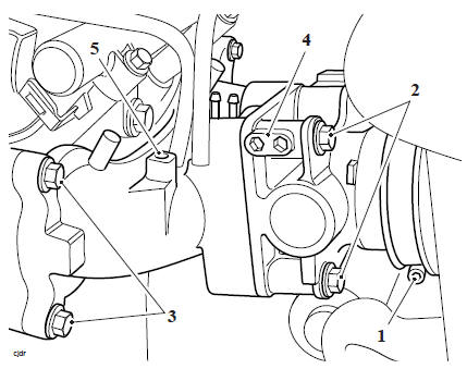
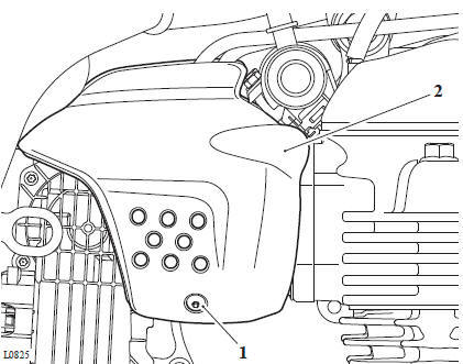
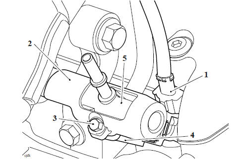
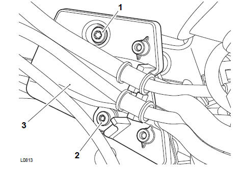
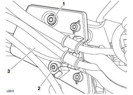
3. Disconnect the electrical connector from the fuel injectors.
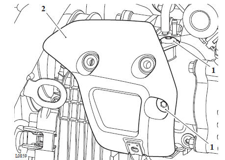
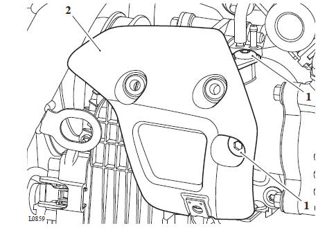
4. Remove the two fixings securing the fuel rail and fuel rail covers to the cylinder head. Collect the spacers between the fuel rail and cylinder head and the two covers.
1. Electrical connector (right hand side shown) 2. Fuel rail cover (right hand side shown) 3. Fixing (right hand side shown) 4. Spacer 5. Fuel rail
5. Gently ease the fuel rail and injectors upwards to release them from the cylinder head.
Note
- The fuel injectors are not to be removed from the fuel rail unless they are to be replaced.
- If the injectors require replacing continue from step 6.
- Note the position of the retaining clip for installation.
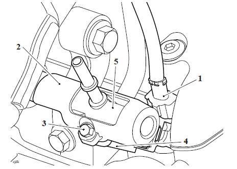
6. Carefully remove the retaining clips securing the fuel injectors to the fuel rail.
7. Ease each injector from the fuel rail.
- Retaining clip
- Injector
- Fuel rail
Note
- If the fuel injectors have been removed from the fuel rail, continue from step 1 and omit steps 3 and 4.
- If the fuel injectors have not been removed, continue from step 3.
1. Lightly lubricate the O-rings with clean engine oil and fit the new fuel injectors to the fuel rail.
2. Fit the retaining clip for each fuel injector as noted for removal.
1. Retaining clip 2. Fuel injector 3. Fuel rail
3. Remove and discard the O-ring on the fuel injector.
4. Fit a new O-ring using finger pressure only.
5. Lightly lubricate the O-ring on the injectors and fit the injector/fuel rail assembly to the cylinder head, orientating each injector such that the electrical connection is facing upwards.
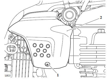
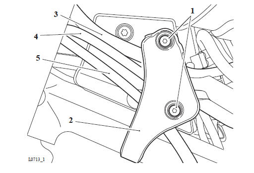
6. Fit the spacers between the fuel rail and cylinder head, fit the fuel rail covers, fit and tighten the fixings to 6 Nm.
1. Electrical connector (right hand side shown) 2. Fuel rail cover (right hand side shown) 3. Fixing (right hand side shown) 4. Spacer 5. Fuel rail
7. Connect the electrical connectors to the fuel injectors.
Note
For the USA and Canadian Markets only, there is an ignition master switch and bracket assembly secured to the left hand side of the throttle body by the finisher mounting and its fixings.
8. Fit the mountings for the air intake finisher and tighten its new fixings to 3 Nm.
- Fixings
- Mounting (right hand side shown)
9. Fit the air intake finishers and tighten the new fixing to 1.5 Nm.
- Fixing
- Air intake finisher (right hand side shown)
Perform the following operations:
- Side Panels
- Exhaust Silencer - Installation
- Fuel Tank - Installation
- Battery - Installation
- Seat - Installation
WARNING
Before starting work, ensure the motorcycle is stabilised and adequately supported. This will help prevent it from falling and causing injury to the operator or damage to the motorcycle.
Note
The engine ECM is located at the rear of the battery box.
Perform the following operations:
- Seat - Removal
- Battery - Removal
- Rear Mudguard - Removal
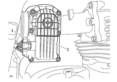
1. Remove the engine electronic control module (ECM) strap and detach it from the battery box.
2. Disconnect the two electrical connectors and remove the engine ECM (see Electrical Connectors).
- Electrical connectors
- Engine ECM
- Strap
WARNING
Before starting work, ensure the motorcycle is stabilised and adequately supported. This will help prevent it from falling and causing injury to the operator or damage to the motorcycle.
1. Reconnect the engine ECM connectors (see Electrical Connectors).
2. Secure the engine ECM to the battery box with the strap.
Perform the following operations:
- Rear Mudguard - Installation
- Battery - Installation
- Seat - Installation
CAUTION
The fixings for the throttle actuator motor are marked with yellow paint and must not be loosened or removed.
If the fixings have been loosened or removed the throttle body assembly must be replaced as there are no means to reset the throttle actuator motor to its correct position.
The throttle actuator motor is an integral part of the throttle body and cannot be adjusted or replaced separately.
WARNING
Before starting work, ensure the motorcycle is stabilised and adequately supported. This will help prevent it from falling and causing injury to the operator or damage to the motorcycle.
Perform the following operations:
- Seat - Removal
- Battery - Removal
- Fuel Tank - Removal
1. Remove the right hand handlebar end weight. Discard the fixing.
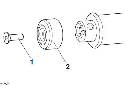
- Fixing
- End weight
Note
- The anti-tamper fixings on the twist grip housing must not be loosened or removed.
- If the anti-tamper fixings have been loosened or removed any warranty claims for the twist grip housing will not be honoured.
2. Release the fixings and remove the clamp for the twist grip housing from the handlebar.
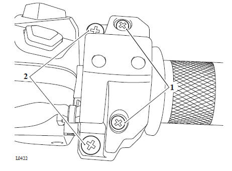
- Anti-tamper fixings
- Fixings
Note
Note the position and orientation of the twist grip to its housing for installation.
3. Slide the twist grip off the handlebar.
WARNING
Before starting work, ensure the motorcycle is stabilised and adequately supported. This will help prevent it from falling and causing injury to the operator or damage to the motorcycle.
1. Align the twist grip to the twist grip position sensor as noted for removal.
2. Fit the twist grip clamp. Ensure the locating lug fits into its hole on the handlebar.
- Locating lug
- Hole
- Twist grip clamp
3. Fit the fixings and tighten, upper one first, to 2.5 Nm.
4. Refit the right hand handlebar end weight and spacer. Tighten the new fixing to 5 Nm.
- Fixing
- Handlebar end weight
- Handlebar
- Twist grip
Perform the following operations:
- Battery - Installation
- Seat - Installation
WARNING
Before starting work, ensure the motorcycle is stabilised and adequately supported. This will help prevent it from falling and causing injury to the operator or damage to the motorcycle.
Perform the following operations:
- Seat - Removal
- Battery - Removal
- Twist Grip - Removal
Note
- Note the orientation of the twist grip position sensor for installation.
- Note the routing of the twist grip harness and its rubber bands for installation.
- Note the routing of the brake lines, clutch cable and harnesses through the headstock tidy for installation.
1. Release the fixings and remove headstock tidy outer cover.
- Fixings
- Outer cover
- Front brake master cylinder brake line
- Front brake caliper brake line
- Clutch cable
2. Release the fixings and remove the headstock centre cover.
- Fixing M5
- Fixing M4
- Centre cover
3. Disconnect the twist grip position sensor electrical connector from the main harness and route the harness to the twist grip.
- Twist grip position sensor electrical connector
4. Slide the twist grip position sensor off the handlebar.
WARNING
Before starting work, ensure the motorcycle is stabilised and adequately supported. This will help prevent it from falling and causing injury to the operator or damage to the motorcycle.
1. Slide the twist grip position sensor onto the handlebar in the orientation noted for removal.
2. Route the twist grip harness to the main harness as noted for removal.
3. Connect the twist grip position sensor electrical connector to the main harness.
- Twist grip position sensor electrical connector
4. Position the harnesses to the headstock tidy as noted for removal. Fit the headstock centre cover and tighten the M5 fixing to 5 Nm and the M4 fixing to 3 Nm.
- Fixing M5
- Fixing M4
- Centre cover
5. Position the front brake lines and the clutch cable to the headstock tidy as noted for removal.
6. Fit the headstock tidy outer cover and tighten the fixings to 3 Nm.
- Fixings
- Outer cover
- Front brake master cylinder brake line
- Front brake caliper brake line
- Clutch cable
Perform the following operations:
- Twist Grip - Installation
- Battery - Installation
- Seat - Installation
WARNING
Move the handlebars to left and right full lock while checking that the brake hose, clutch hose and electrical harnesses do not bind or that the steering feels tight or difficult to turn. A hose, cable or harness that binds, or steering that is tight/difficult to turn will restrict the steering and may cause loss of control and an accident.
Check for correct operation of the front brake, clutch and twist grip. Check that the brake hose, clutch hose and electrical harnesses do not bind or restrict the steering when the handlebars are turned from lock-to-lock. Rectify as necessary.
WARNING
Before starting work, ensure the motorcycle is stabilised and adequately supported. This will help prevent it from falling and causing injury to the operator or damage to the motorcycle.
Perform the following operations:
- Seat - Removal
- Battery - Removal
- Right hand Side Panels
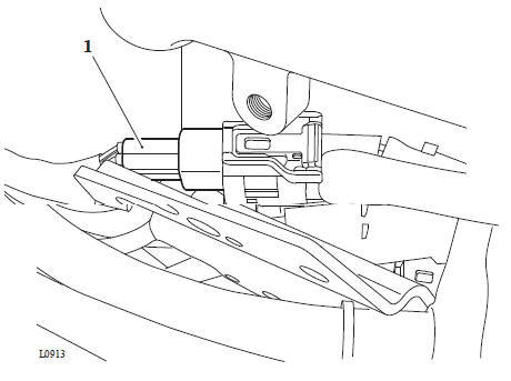
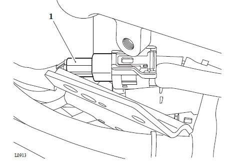
1. Disconnect the electrical connector from the sensor.
2. Remove the fixing and remove the sensor from the airbox.
- Fixing
- Electrical connector
- Airbox
See also:
 Triumph Scrambler 1200 XC - Service manual > Removal and Installation - Fuel and Air Components
Fuel Cap Cover - Removal Fuel Cap Cover - Installation Fuel Tank - Removal
Triumph Scrambler 1200 XC - Service manual > Front Suspension
1. Fit the sensor to the airbox and tighten thefixing to 1.5 Nm. 2. Reconnect the electrical connector to the sensor. Perform the following operations: Refit the right hand Side Panels Battery - Installation Seat - Installation
 Ducati Scrambler
 Fantic Caballero 500
 Indian FTR 1200
 Moto Guzzi V85 TT
 Royal Enfield Bullet Trials Works Replica
 Triumph Scrambler 1200 XE
 Triumph Street Scrambler
 Yamaha XSR700
 Ducati Scrambler 800
 Moto Guzzi V85 TT
 Triumph Scrambler 1200 XC