 Indian FTR 1200 - Owner's Manual > Front Wheel Removal / Installation
WARNING This procedure requires raising and supporting the motorcycle so that the front wheel is off the ground.
Precautions should be taken to ensure the motorcycle is properly stabilized at all times. Failure to properly support motorcycle may result in personal injury or damage to the motorcycle.
CAUTION Do not twist the brake hose or brake line. Do not allow calipers to hang from the brake hose. Secure calipers in such a way to avoid hose damage.
1. Secure the motorcycle in an upright position with tie-down straps and a platform jack positioned beneath the engine cases.
IMPORTANT Do not operate the front brake lever with the calipers or wheel removed.
REMOVAL
2. Remove front brake calipers.
3. Loosen axle pinch bolts 1 on lower right fork leg.
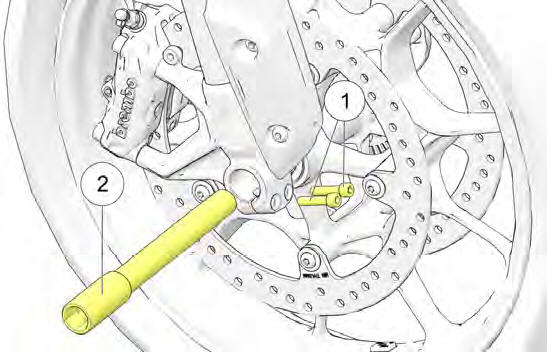
4. Support wheel and remove axle 2 with 22 mm hex drive.
Spacers are loosely retained by the dust seals, but may fall out after wheel has been removed.
INSTALLATION
5. Install front wheel and spacers into fork.
6. Install the axle and torque to specification.
TORQUE
Axle (front fork): 55 (75 N*m)
7. Cycle the front suspension. Tighten axle pinch bolts to specification.
TORQUE
Axle Pinch Fasteners: 14 (19 N*m) Tighten each screw once after initial torque
8. Reinstall front brake calipers.
TIRES
WARNING Operating the motorcycle with incorrect tires, incorrect tire pressure or excessively worn tires could cause loss of control or accident. Underinflation can cause a tire to overheat and result in a tire failure. Always use the correct size and type of tires specified by INDIAN MOTORCYCLE for your vehicle. Always maintain proper tire pressure as recommended in the rider's manual and on safety labels.
TIRE REPLACEMENT
Tires, rims, and air valves must be correctly matched to wheel rims. Use only the proper size tires specified with the same or higher load ratings. INDIAN MOTORCYCLE-recommended tires provide proper clearance between fenders, swingarm, drive chain and other components. See the Specifications section for details.
WARNING Mismatched tires, rims and air valves may result in damage to the tire bead during mounting or may allow the tire to slip off the rim, possibly resulting in tire failure.
TIRE CONDITION
Inspect the tire sidewalls, road contact surface, and tread base for cuts, punctures, and cracking. Replace damaged tires immediately. See the INDIAN MOTORCYCLE Service Manual or an authorized INDIAN MOTORCYCLE dealer or other qualified dealer.
TIRE TREAD DEPTH
Replace any tire with a tread depth of less than 1/16 inch (1.6 mm).
Tread wear indicators are located in at least three places on the tread circumference and become visible at a tread depth of approximately 1/16 inch (1.6 mm). The tread wear indicators appear as a solid band across the tread.
You may also use a depth gauge or an accurate ruler to measure the depth of the center tire tread on both front and rear tires.
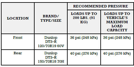
TIRE PRESSURE
Always check and adjust tire pressure when tires are cold. Do not adjust tire pressure immediately after riding. Wait at least 3 hours after riding to check pressure. If pressure checked and adjusted while tires are warm, the pressure will drop as tires cool and result in under inflation.
Adjust tire pressure as recommended for the total weight of your intended load (see following chart). For more information, refer to the manufacturing information label located on the front frame downtube.
WARNING Do not exceed the maximum recommended inflation pressure to seat the bead. Tire or rim failure may result.
SEAT REMOVAL
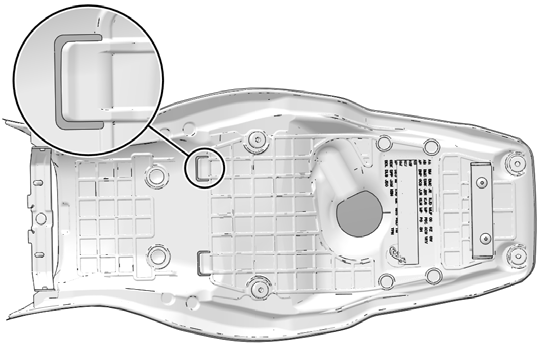
1. Remove both Passenger Grab Handle Fasteners 1 and Grab Handles 2.
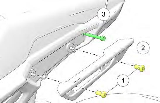
2. Remove Seat Fasteners 3.
3. Lift up on the rear of the seat and pull rearward to disengage the front of the seat from frame.
SEAT INSTALLATION
1. Identify two tabs located on the underside of the seat.
2. Slide the tabs shown above beneath the support bracket and into the front mounting bracket.
TIP Pull up on the rear of the seat prior to installing fasteners to assure front tab engagement.
3. Secure the rear of the seat with the two fastener screws.
TORQUE
Seat Fasteners: 84 in-lbs (9.5 Nm)
4. Reinstall the two passenger grab handles with two screws per handle.
TORQUE
Passenger Grab Handle Fasteners: 19 (26 N*m)
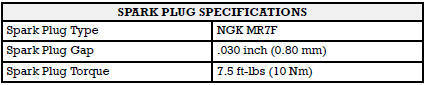
SPARK PLUGS
See your dealer for spark plug inspections and replacement at the intervals specified in the Periodic Maintenance Table.
HEADLIGHT AIM INSPECTION
On LOW beam, the top of the horizontal cut-off of the light beam 1 should be 7 in. (17.8 cm) lower than the center of the headlight bulb and centered straight ahead at 32 ft. 10 in. (10 m).
1. Verify that tire pressure is at specification.
2. Verify that rear suspension ride height (preload) is at specification.
3. Position the motorcycle on a level surface with the headlight 32 ft. 10 in. (10 m) from a wall.
4. With the operator and passenger (if applicable) on board, bring the motorcycle to the fully upright position.
5. Start the engine and switch the headlight to low beam. Observe the headlight aim on the wall.
6. Make any necessary adjustments to headlight aim.
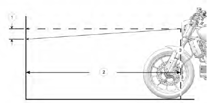
- Stock ECE and CCC compliant measure distance = 7 in. (17.8 cm)
Optional North American only measure distance = 4 in. (10.2 cm) - Measure distance = 32 ft. 10 in. (10.0 m)
- Headlight Center
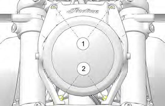
HEADLIGHT AIM ADJUSTMENT
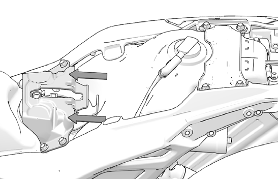
1. To adjust the headlamp vertically, loosen the two housing mount fasteners 1 (one on each side) and pivot the housing upward or downward. Tighten the fasteners to specification.
TORQUE
Headlight Adjustment Fastener: 25 (34 N*m)
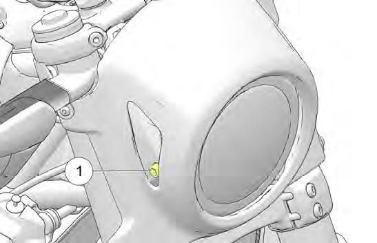
HEADLIGHT COWL REMOVAL (IF APPLICABLE)
1. Remove and retain four screws 1 and four washers 2 from the headlight cowl.
2. Remove headlight cowl and set aside for reinstallation.
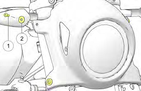
HEADLIGHT REMOVAL
1. Remove and retain two screws 1 from top of headlight bracket.
2. Remove and retain two screws 2 from bottom of headlight bracket.
TIP Turn handlebars lock-to-lock to access two screws A from rear-side.
3. With headlight assembly unmounted, tilt assembly forward and slide electronic throttle control (ETC) connection off push-pin clip. It is not necessary to disconnect harnesses.
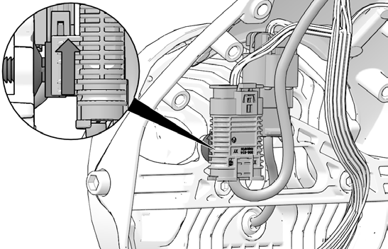
4. Disconnect headlight from chassis harness. Headlight connector will remain installed onto push-pin clip.
5. Carefully set headlight assembly aside on soft surface as to not scratch finished surfaces.
See also:
 Indian FTR 1200 - Owner's Manual > Brake Fluid Precautions
WARNING Using the wrong fluid or allowing air or contaminants into the fluid system can damage the system seals or result in a malfunction that could lead to serious injury or death. Use only DOT 4 brake fluid from a sealed container.
Indian FTR 1200 - Owner's Manual > Battery
The motorcycle battery is a sealed, maintenance-free battery. Do not remove the battery cap strip for any reason. Keep the battery connections clean and tight at all times. WARNING Battery electrolyte is poisonous. It contains sulfuric acid. Serious burns can result from contact with skin, eyes or clothing.
 Ducati Scrambler
 Fantic Caballero 500
 Indian FTR 1200
 Moto Guzzi V85 TT
 Royal Enfield Bullet Trials Works Replica
 Triumph Scrambler 1200 XE
 Triumph Street Scrambler
 Yamaha XSR700
 Ducati Scrambler 800
 Moto Guzzi V85 TT
 Triumph Scrambler 1200 XC