 Ducati Scrambler 800 - Service manual > Gearbox assembly: gearbox shafts
Reassembling the gearbox assembly
To refit the gearbox components follow the procedure under chapter "Closing the crankcase" relating to the reassembly of the crankcase.
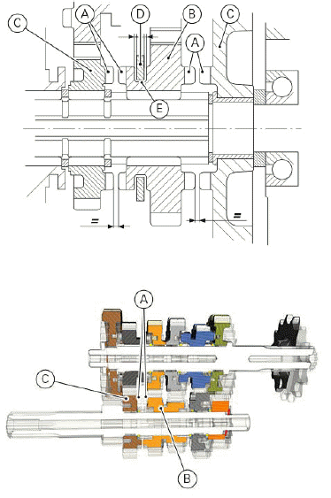
As a final practical test, ensure that with the gearbox in neutral the front coupling dogs (A) of sliding gears (B) are equidistant on both sides with respect to the corresponding coupling dogs on the fixed gears (C).
Check also that there is always a small amount of clearance between fork (D) and relative groove (E) on sliding gear (B) when engaging the gears.
Refit the engine in the frame (Refitting the engine).
Reassembling the gearbox shafts
Reassemble the gears on the gearbox shafts by reversing the disassembly procedure.
Take particular care when installing the idler gears.
The assembly of the 3rd and 4th speed gears and the relative fixing components on the secondary shaft is given as an example.
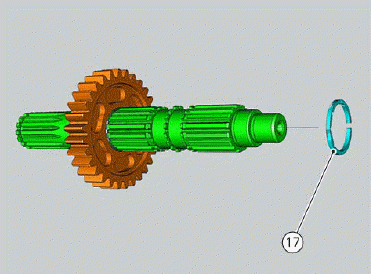
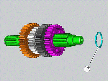
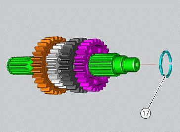
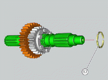
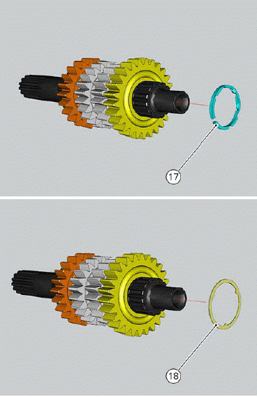
Fit the snap ring (17), checking that it is fully inserted into its groove on the shaft.
Push the snap ring into position with a suitable size tubular drift.
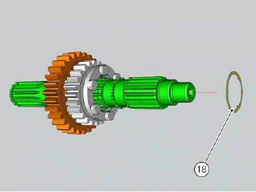
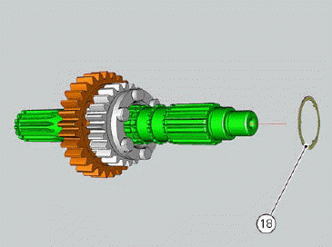
Slide the three-pointed washer (18) over the shaft until it locates against the snap ring you have just fitted.
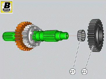
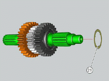
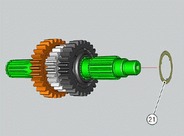
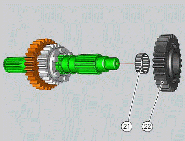
To fit the roller bearing cage (21) onto the shaft, first lubricate it with plenty of grease (of recommended type) and then open it slightly to make it easier to slide on to the shaft.
Fit the 3rd speed gear (22).
Fit the three-pointed washer (21), which has a bigger outer diameter than the other one (18), in the gear.
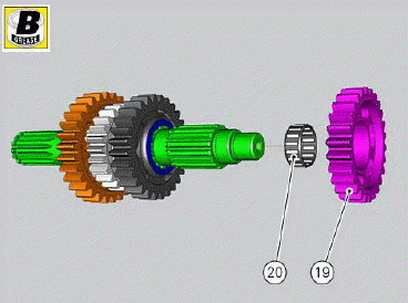
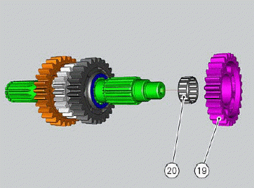
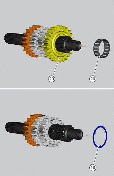
Fit another roller bearing cage (20) using the method already described.
Fit the 4th speed gear (19).
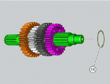
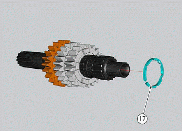
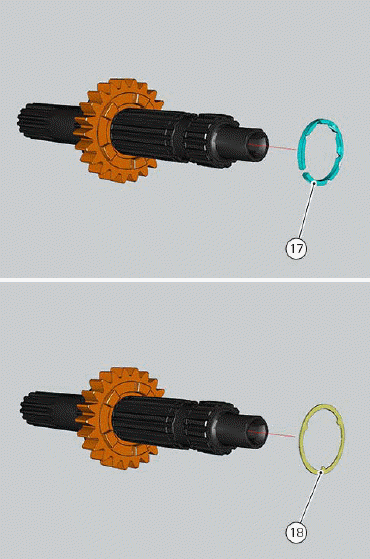
Fit another three-pointed washer (18) and another snap ring (17) into the shaft.
Push it inside its seat using the previously used drift.
Inspecting the fork selector drum
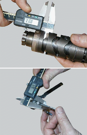
Use a gauge to measure the clearance between fork pin and the groove on the selector drum.
If the service limit has been exceeded, determine which part must be replaced by comparing these dimensions with those of new components.
Also check the wear on the drum support pins; these must not show any signs of scoring, burrs, or deformation.
Turn the drum in the crankcase to establish the extent of radial play.
If play is excessive, change whichever part is most worn.
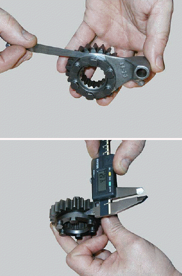
Inspecting the gear selector forks
Visually inspect the gear selector forks. Bent forks must be replaced as they may lead to difficulties in gear changing or may suddenly disengage when under load.
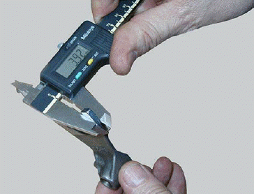
Use a feeler gauge to check the clearance of each fork in its gear groove.
If the service limit has been exceeded, check whether or not it is necessary to replace the gear or the fork by referring to the limits specified for each part.
Overhauling the gearbox
Check the condition of the front coupling dogs of the gears. They must be in perfect condition and with no sign of wear on the edges of the teeth.
The idler gears must rotate freely on their shafts.
When refitting, make sure the circlips are correctly positioned.
Check the needle roller bearings for wear.
The threads and splines of the shafts must be in perfect condition.
Also check that the component parts of the gear selector mechanism are in good condition.
Engage the gears and check that the gearchange mechanism does not stick (selector fork-gear groove, and fork pin-desmodromic drum groove) due to incorrect end float.
Restore the correct end float by shimming the gearbox shafts and the selector drum with suitable shims.
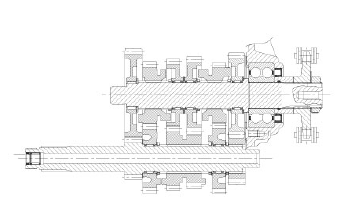
Disassembling the gearbox shafts
Important Take care not to invert the shim position upon reassembly: this would potentially lead to jamming when using the gear selector control, making it necessary to reopen the crankcase.
Disassembling the gearbox secondary shaft
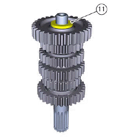
Remove the chain-side washer (11) and the clutch shim washer (12) from the secondary shaft.
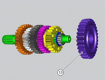
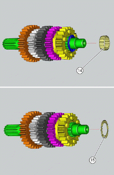
Withdraw the first speed driven gear (13) with the roller cage (14) and the shim (15).
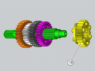
Remove the fifth speed driven gear (16).
Use two flat blade screwdrivers to remove the snap ring (17) from its seat, taking care not to damage the shaft surface.
Remove the snap ring (17) and the splined washer (18).

Remove the fourth speed driven gear (19) with its roller bearing cage (20) and splined washer (21).
Remove the third speed driven gear (22) with its roller bearing cage (20) and splined washer (18).
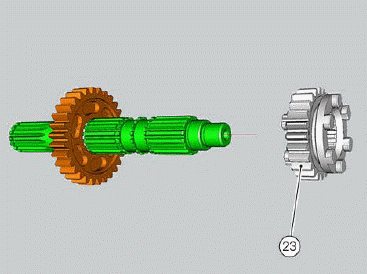
Remove snap ring (17) and slide out the sixth speed driven gear (23).
Remove the snap ring (17) and withdraw the splined washer (18) and the second speed driven gear (24).

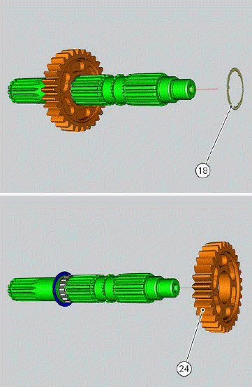
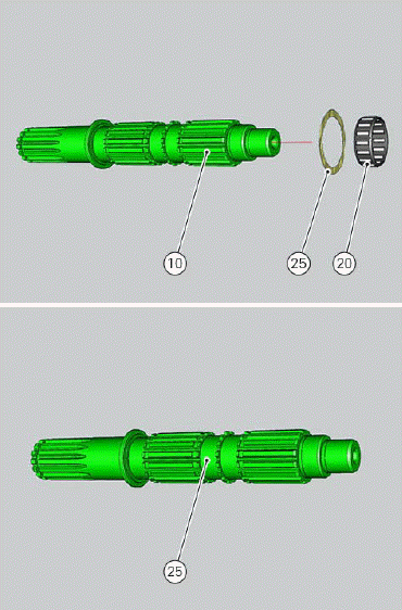
Withdraw the roller bearing cage (20) and the shim (25). All the components have thus been removed from gearbox secondary shaft (10).
Disassembling the gearbox primary shaft
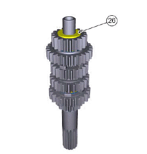
Remove washer (26) from the primary shaft.
Remove the second speed driving gear (28). Use two screwdrivers to prise out the snap ring (17) and the splined washer (18).
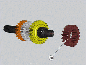
Important Take care to avoid damaging the surface of the shaft while removing the snap ring.
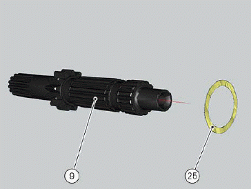
Remove the sixth speed driving gear (29) with its roller cage (20).
Then remove the splined washer (18) and the snap ring (17).
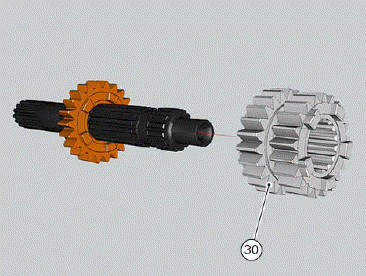
Withdraw the third and fourth speed driving gear (30).
Remove the snap ring (17) and the splined washer (18).
Remove the fifth speed driving gear (31) with its roller cage (20).
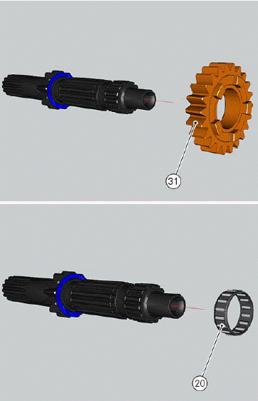
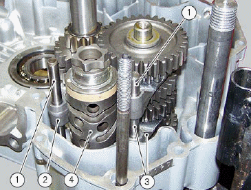
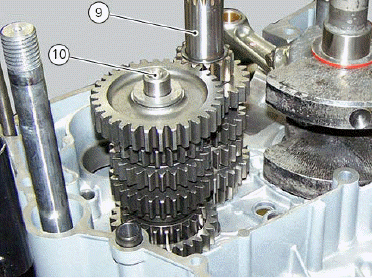
Slide out washer (25) from the primary shaft (9).
Removing the gearbox assembly
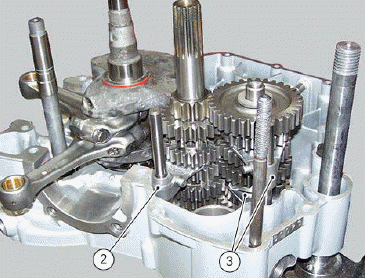
Withdraw the selector fork shafts (1).
Move the forks (2) and (3) to disengage them from the slots in the selector drum.
Remove fork selector drum (4) paying attention not to invert the shims (5) and (6) fitted on the shaft.
Once removed, it is possible to replace block ring (7) and special needles (8).
Remove gear selector forks (2) and (3).
Remove the gearbox primary (9) and secondary (10) shafts complete with gears, taking care to recover the shim washers on the ends of the shafts.
If the bearing inner rings are left on the shafts, slide them off the ends of the gearbox primary (9) and secondary (10) shafts.
Remove them from the shaft ends and fit them in the relevant bearings on the crankcase half.
See also:
 Ducati Scrambler 800 - Service manual > Gearbox assembly: linkages
Refitting the gearchange mechanism Position the gearbox drum selector fork in the centre of the gear rollers. Position the complete gearchange mechanism (3) in the chain-side crankcase half.
 Ducati Scrambler
 Fantic Caballero 500
 Indian FTR 1200
 Moto Guzzi V85 TT
 Royal Enfield Bullet Trials Works Replica
 Triumph Scrambler 1200 XE
 Triumph Street Scrambler
 Yamaha XSR700
 Ducati Scrambler 800
 Moto Guzzi V85 TT
 Triumph Scrambler 1200 XC