 Ducati Scrambler 800 - Service manual > Gearbox assembly: linkages
Refitting the gearchange mechanism
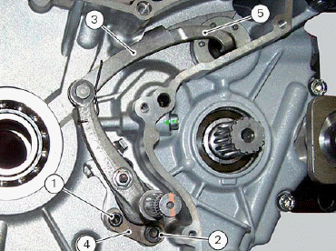
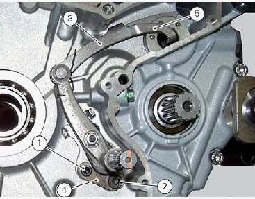
Position the gearbox drum selector fork in the centre of the gear rollers.
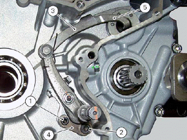
Position the complete gearchange mechanism (3) in the chain-side crankcase half.
Insert the screws (1) and (2) with the spacer (4).
Temporarily fit gearchange lever (or a service lever) and sprocket and shift to neutral gear.
Set tool (A) part no. 88713.3334 on the gearbox pawl.
Position the tool by inserting the engine pin (25) inside the tool hole; engage tool pin (26) in the gearbox pawl by pressing with your hand in the indicated point.
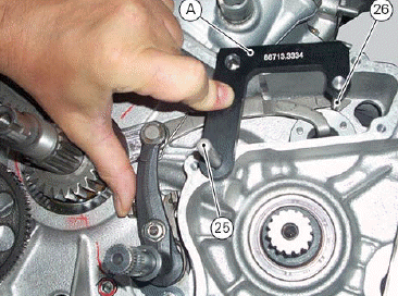
In this position first tighten the screw (2) to a torque of 36 Nm (Min. 34 Nm - Max. 38 Nm) and then the screw (1) to a torque of 16 Nm (Min. 15 Nm - Max. 17 Nm).
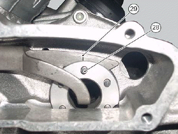
Remove the tool and check that pin (28) on the gearbox drum is aligned with notch (29) on the gearchange pawl.
With the gearbox in neutral, check that the lever travel is the same when shifting up and down.
The same should apply when a gear is engaged.
Operate the gearchange lever and turn the front sprocket at the same time to check that all the gears engage when shifting up and down.
Remove the gearchange lever.
Reassembling the gearchange mechanism
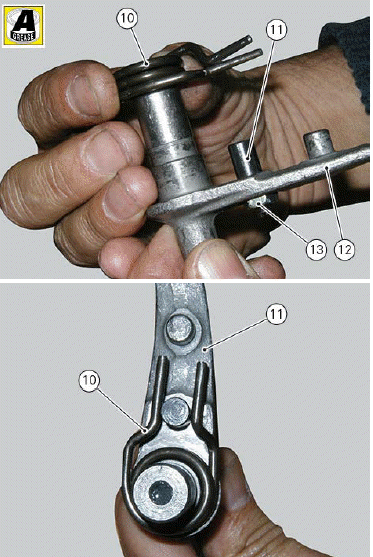
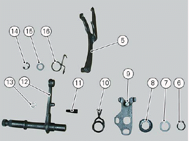
If during the removal procedure the gearchange mechanism has been removed, it is necessary to engage the spring (10) on shaft (12) in the position indicated in the picture.
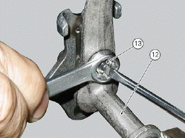
Use the specified product to grease the threaded end of the eccentric pin (12) and fit it from the upper side of the gearchange lever and fix it with nut (13).
Screw the nut fully home (without tightening).
Insert shaft (12) in plate (9), position washer (7) and block with the snap ring (6).
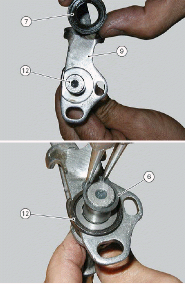
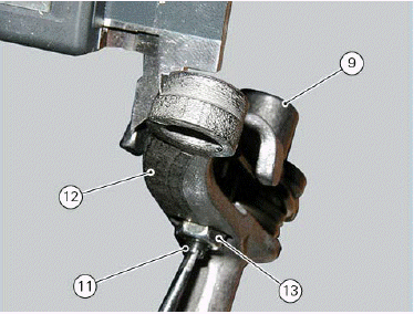
Position lever (12) correctly according to the plate (9) position.
The lever pin must be equidistant from the plate edges; to modify its position, work on the suitable eccentric pin (11) after loosening lock nut (13).
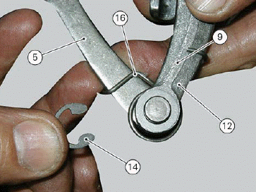
Position spring (16) between shaft (12) and fork (5).
Fit ring (14) to block the coupled elements.
Check that the spring (16) is installed correctly as shown in the figure.
Then tighten nut (13) to a torque of 10 Nm (Min. 9 Nm - Max. 11 Nm)
Refit the flywheel/generator assembly and the generator cover (Refitting the flywheel/generator assembly).
Refit the gear shift (Refitting the gear shift).
Refit the front sprocket (Refitting the front sprocket).
Fill with engine oil (Changing the engine oil and filter cartridge).
Refitting the gear interlock plunger and ratchet
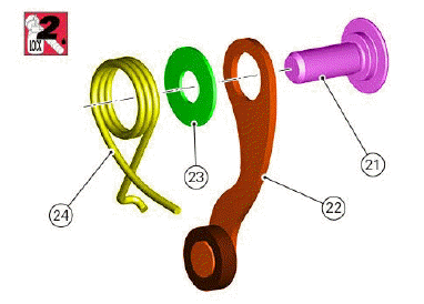
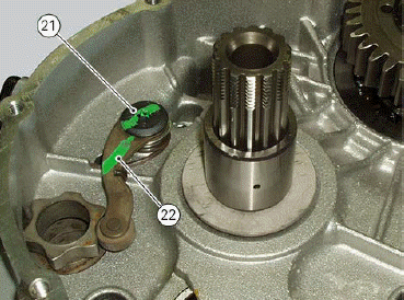
On the retaining screw (21), fit the gear ratchet (22), orienting it as shown in the figure, the washer (23) with the sharp edge side facing the clutch-side crankcase half, and the spring (24), positioning it so that the hook end is facing the gear ratchet.
Apply threadlocker on screw thread.
Start the screw in the crankcase half. Position spring end against the crankcase half rib.
Tighten screw (21) to a torque of 18 Nm (Min. 16 Nm - Max. 20 Nm).
Manually move the gear ratchet to check for proper spring operation.
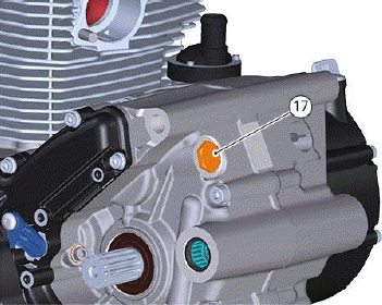
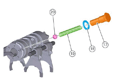
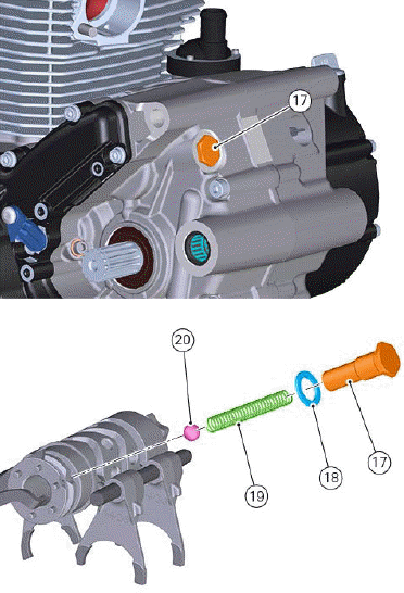
Grease and then fit the ball (20), spring (19) and seal (18) to the gear interlock plunger (17) and screw the plunger on the casing.
Tighten the gear interlock plunger to a torque of 30 Nm (Min. 27 Nm - Max. 33 Nm)
Refit the clutch unit (Refitting the clutch).
Reconnect the oil pressure sensor.
Fill the engine with oil (Changing the engine oil and filter cartridge).
Disassembling gear interlock plunger and ratchet
Drain the engine oil (Changing the engine oil and filter cartridge).
Disconnect the oil pressure sensor.
Remove the clutch cover (Removing the clutch cover).
Remove the clutch unit (Removing the clutch).
Undo the interlock plunger screw (17) and remove the seal (18), the spring (19) and the ball (20).
Undo the clutch-side crankcase half screw (21) and remove the ratchet (22), the washer and the spring.
Removing the gearchange mechanism
Drain the engine oil (Changing the engine oil and filter cartridge).
Remove the gear shift (Removing the gear shift).
Remove the front sprocket (Removing the front sprocket).
Remove the generator cover (Removing the generator cover).
Undo the fixing screws (1) and (2) of the complete gearchange mechanism (3).
Remove screws (1) and (2), plate (4) and slide out the gearchange mechanism with control shaft, spring and plate.
Disassembling the gearchange mechanism
If it proves necessary to change components, disassemble the gearchange mechanism as shown in the picture.
See also:
 Ducati Scrambler 800 - Service manual > Gearbox assembly: gearbox shafts
Reassembling the gearbox assembly To refit the gearbox components follow the procedure under chapter "Closing the crankcase" relating to the reassembly of the crankcase.
 Ducati Scrambler
 Fantic Caballero 500
 Indian FTR 1200
 Moto Guzzi V85 TT
 Royal Enfield Bullet Trials Works Replica
 Triumph Scrambler 1200 XE
 Triumph Street Scrambler
 Yamaha XSR700
 Ducati Scrambler 800
 Moto Guzzi V85 TT
 Triumph Scrambler 1200 XC