 Triumph Street Scrambler - Owner's Manual > Ignition Switch/Steering Lock
Warning
For reasons of security and safety, always turn the ignition to the OFF or PARK position and remove the key when leaving the motorcycle unattended.
Any unauthorised use of the motorcycle may cause injury to the user, other road users and pedestrians and may also cause damage to the motorcycle.
Warning
With the key in the LOCK or P position the steering will become locked.
Never turn the key to the LOCK or P positions while the motorcycle is moving as this will cause the steering to lock. Locked steering will cause loss of motorcycle control and an accident.
- Ignition switch/Steering lock
- ON position
- OFF position
- LOCK position
- PARK position
Switch Operation
This is a four position, key operated switch. The key can be removed from the switch only when it is in the OFF, LOCK or P (PARK) position.
TO LOCK: Turn the steering fully to the left, turn the key to the OFF position, push and fully release the key, then rotate it to the LOCK position.
PARKING: Turn the key from the LOCK position to the P position. The steering will remain locked.
Note:
Do not leave the steering lock in the P position for long periods of time as this will cause the battery to discharge.
Engine Immobiliser
The ignition switch housing acts as the antenna for the engine immobiliser.
When the ignition switch is turned to the OFF position and the ignition key is removed, the engine immobiliser is on
The engine immobiliser is turned off when the ignition key is in the ignition switch and it is turned to the ON position.
Ignition Key
Warning
Additional keys, key rings/chains or items attached to the ignition key may interfere with steering, leading to loss of motorcycle control and an accident.
Remove all additional keys, key rings/ chains and items from the ignition key before riding the motorcycle.
Caution
Additional keys, key rings/chains or items attached to the ignition key may cause damage to the motorcycle's painted or polished components.
Remove all additional keys, key rings/ chains and items from the ignition key before riding the motorcycle.
Caution
Do not store the spare key with the motorcycle as this will reduce all aspects of security.
- Key number tag
In addition to operating the ignition switch/steering lock, the ignition key is required to operate the seat lock and fuel tank cap.
When the motorcycle is delivered from the factory, two ignition keys are supplied together with a small tag bearing the key number. Make a note of the key number and store the spare key and key number tag in a safe place away from the motorcycle.
A transponder is fitted within the ignition keys to turn off the engine immobiliser. To make sure the immobiliser functions correctly, always have only one of the ignition keys near the ignition switch. Having two ignition keys near the switch may interrupt the signal between the transponder and the engine immobiliser. In this situation the engine immobiliser will remain active until one of the ignition keys is removed.
Always get replacement keys from your authorised Triumph dealer. Replacement keys must be 'paired' with the motorcycle's immobiliser by your authorised Triumph dealer.
Right Handlebar Switches
Street Twin, Street Cup, Street Scrambler and Thruxton R
- Engine start/stop switch
- STOP position
- RUN position
- START position
- Hazard warning light switch
Thruxton, Bonneville T100 and Bonneville T120
- Engine start/stop switch
- STOP position
- RUN position
- START position
- MODE button (Thruxton and Bonneville T120 only)
- Hazard warning light switch
STOP Position
The STOP position is for emergency use.
If an emergency arises which requires the engine to be stopped, move the engine start/stop switch to the STOP position.
Note:
Although the engine stop switch stops the engine, it does not turn off all the electrical circuits and may cause difficulty in restarting the engine due to a discharged battery. Ordinarily, only the ignition switch should be used to stop the engine.
Caution
Do not leave the ignition switch in the ON position unless the engine is running as this may cause damage to electrical components and will discharge the battery.
RUN Position
In addition to the ignition switch being turned to the ON position, the engine start/stop switch must be in the RUN position for the motorcycle to operate.
START Position
The START position operates the electric starter. For the starter to operate, the clutch lever must be pulled to the handlebar and the start/stop switch in the START position.
Note:
Even if the clutch lever is pulled to the handlebar, the starter will not operate if the side stand is down and a gear is engaged.
MODE Button (if fitted)
The MODE button allows throttle response adjustment. Press and release the MODE button to select one of the different rider modes available
Hazard Warning Lights
To turn the hazard warning lights on or off, press and release the hazard warning light switch.
The ignition must be switched ON for the hazard warning lights to function.
The hazard warning lights will remain on if the ignition is switched OFF, until the hazard warning light switch is pressed again.
Left Handlebar Switches
- SCROLL button
- Horn button
- Direction indicator switch
- MODE button (Thruxton R only)
- Daytime Running Lights (DRL) switch (if fitted)
- High beam button
SCROLL Button
The SCROLL button is used to operate the following functions of the instruments:
- Odometer functions
- Trip reset
- Clock reset
- Traction control functions
Horn Button
When the horn button is pushed, with the ignition switch turned to the ON position, the horn will sound.
Direction Indicator Switch
When the direction indicator switch is pushed to the left or right, the corresponding direction indicators will flash on and off.
The indicators can be cancelled manually. To manually turn off the indicators, press and release the indicator switch in the central position.
MODE Button (if fitted)
The MODE button allows throttle response adjustment. Press and release the MODE button to select one of the different rider modes available
Daytime Running Lights (DRL) Switch (if fitted)
Note:
Daytime running lights are manually operated. They are not automatic.
The daytime running lights or dip beam can be selected with the Daytime Running Lights (DRL) switch.
To select daytime running lights, push the DRL switch forward.
To select dip beam, push the DRL switch rearwards.
When the daytime running lights are turned on, the daytime running lights indicator light will illuminate in the instrument panel.
High Beam Button
When the high beam button is pressed the high beam will be switched on. Each press of the button will swap between dip and high beam.
Note:
If daytime running lights are fitted to the motorcycle, the high beam button has additional functionality.
If the DRL switch is in the daytime running lights position, then press and hold the high beam button to turn the high beam on. It will remain on as long as the button is held in and will turn off as soon as the button is released.
Note:
- A lighting on/off switch is not fitted to this model. The position light, rear light and licence plate light all function automatically when the ignition is turned to the ON position.
- The headlight will function when the ignition switch is turned to the ON position. The headlight will go off while pressing the starter button until the engine starts.
Heated Grips (if fitted)
The heated grips work when the ignition is switched on. However, it is recommended that they are only used when the engine is running to avoid draining the battery.
There are two heat levels; low or high.
- Heated grips button
The heated grips button is located on the left hand grip.
Press the heated grip button to show the current status of the heated grips in the display screen. This is shown for three seconds.
Press the heated grip button whilst the status is showing to select one of the three different heat levels; OFF, Lo (low) or HI (high).
For maximum benefit in cold conditions, use the heated grips on the HI level initially and when the grips have warmed up, change to Lo.
To switch off the heated grips, press and release the button until OFF is shown in the display screen. The heated grips are also switched off when the ignition is switched off.
Low Battery Warning
If heated grips are fitted and are on with the engine not running, over a period of time, the battery voltage may drop below 11.8 Volts and 'LoBAtt' is then shown in the display screen for three seconds.
If the heated grips are on and 'LoBAtt' is shown, then the heated grips are automatically switched off to prevent further discharge of the battery. It is not possible to resume heated grip operation until the engine has been running and the battery voltage has increased above 11.8 Volts.
In the event of a fault, 'HgrOFF' is shown in the display screen and the heated grips are automatically switched off. The heated grips can be switched back on by:
- waiting 25 seconds then switch on the heated grip, or
- turning the ignition switch to the OFF position then back to the ON position.
If 'HgrOFF' remains shown in the display screen, then contact an authorised Triumph dealer to have the fault checked and rectified.
Throttle Control
- Throttle open position
- Throttle closed position
All models have an electronic throttle twist grip to open and close the throttles via the engine control unit.
There are no direct-acting cables in the system.
The throttle grip has a resistive feel to it as it is rolled rearwards to open the throttles. When the grip is released it will return to the throttle closed position by its internal return spring and the throttles will close.
There are no user adjustments for the throttle control.
If there is a malfunction with the throttle control the Malfunction Indicator Light (MIL) becomes illuminated and one of the following engine conditions may occur:
- MIL illuminated, restricted engine RPM and throttle movement
- MIL illuminated, limp-home mode with the engine at a fast idle condition only
- MIL illuminated, engine will not start.
For all of the conditions mentioned contact an authorised Triumph dealer as soon as possible to have the fault checked and rectified.
Brake and Clutch Lever Adjusters
Warning
Do not attempt to adjust the levers with the motorcycle in motion as this may lead to loss of motorcycle control and an accident.
After adjusting the levers, operate the motorcycle in an area free from traffic to gain familiarity with the new lever setting.
Do not loan your motorcycle to anyone as they may change the lever setting from the one you are familiar with causing loss of motorcycle control and an accident.
- Adjuster wheel, clutch lever shown
- Arrow mark
An adjuster is fitted to both the front brake and clutch levers. The adjusters allow the distance from the handlebar to the lever to be changed to one of five positions for the front brake lever or four positions for the clutch lever, to suit the span of the operator's hands.
To adjust the lever, push the lever forward and turn the adjuster wheel to align one of the numbered positions with the arrow mark on the lever holder.
The distance from the handlebar grip to the released lever is shortest when set to number five, and longest when set to number one.
Brake Lever Adjuster - Thruxton R Only
Warning
Do not attempt to adjust the levers with the motorcycle in motion as this may lead to loss of motorcycle control and an accident.
After adjusting the levers, operate the motorcycle in an area free from traffic to gain familiarity with the new lever setting.
Do not loan your motorcycle to anyone as they may change the lever setting from the one you are familiar with causing loss of motorcycle control and an accident.
- Brake lever
- Adjusting screw
To adjust the brake lever, push the lever forward and turn the adjusting screw in to increase the distance or out to shorten the distance from the handlebar.
Fuel Requirement/Refuelling
 Fuel Grade
Your Triumph engine is designed to use unleaded fuel and will give optimum performance if the correct grade of fuel is used. Always use unleaded fuel with a minimum octane rating of 91 RON.
In certain circumstances engine calibration may be required. Always refer to your authorised Triumph dealer.
Caution
The motorcycle can be permanently damaged if it is allowed to operate with the incorrect grade of fuel or incorrect engine calibration. Always make sure the fuel used is of the correct grade and quality. Damage caused by using the incorrect fuel or engine calibration is not considered a manufacturing defect and will not be covered under warranty.
Caution
The exhaust system for this motorcycle is fitted with a catalytic converter to help reduce exhaust emission levels. Use of leaded fuel will damage the catalytic converter. In addition, the catalytic converter can be permanently damaged if the motorcycle is allowed to run out of fuel or if the fuel level is allowed to get very low. Always make sure you have adequate fuel for your journey.
Note:
The use of leaded fuel is illegal in some countries, states or territories.
Refuelling
Warning
To help reduce hazards associated with refuelling, always observe the following fuel safety instructions: Petrol (fuel) is highly flammable and can be explosive under certain conditions. When refuelling, turn the ignition switch to the OFF position.
Do not smoke.
Do not use a mobile telephone.
Make sure the refuelling area is well ventilated and free from any source of flame or sparks. This includes any appliance with a pilot light.
Never fill the tank until the fuel level rises into the filler neck. Heat from sunlight or other sources may cause the fuel to expand and overflow creating a fire hazard.
After refuelling always check that the fuel filler cap is correctly closed.
Because petrol (fuel) is highly flammable, any fuel leak or spillage, or any failure to observe the safety advice given above will lead to a fire hazard, which could cause damage to property, injury to persons or death.
Fuel Tank Cap
- Fuel tank cap
To open the fuel tank cap: Remove the cover or lift up the flap.
Insert the key into the lock and turn the key clockwise.
Rotate the cap anticlockwise and lift clear of the tank filler neck.
To close and lock the cap: Align the cap to the tank filler neck and rotate the cap clockwise until the cap seals against the filler neck.
In the fully closed position, a ratchet mechanism prevents overtightening of the cap by allowing the outer part of the cap to turn independently of the internal part.
Turn the key anticlockwise to lock and withdraw the key.
Replace the cover.
Filling the Fuel Tank
Warning
Overfilling the tank can lead to fuel spillage.
If fuel is spilled, thoroughly clean up the spillage immediately and dispose of the materials used safely.
Take care not to spill any fuel on the engine, exhaust pipes, tyres or any other part of the motorcycle.
Because fuel is highly flammable, any fuel leak or spillage, or any failure to observe the safety advice given above may lead to a fire hazard, which could cause damage to property and injury or death to persons.
Fuel spilled near to, or onto the tyres will reduce the tyres' ability to grip the road. This will result in a dangerous riding condition potentially causing loss of motorcycle control and an accident.
Caution
Avoid filling the tank in rainy or dusty conditions where airborne material can contaminate the fuel.
Contaminated fuel may cause damage to fuel system components.
Fill the fuel tank slowly to help prevent spillage. Do not fill the tank to a level above the bottom of the filler neck. This will make sure there is enough air space to allow for fuel expansion if the fuel inside the tank expands through absorption of heat from the engine or from direct sunlight.
- Fuel filler neck
- Maximum fuel level
After refuelling always check that the fuel filler cap is correctly closed.
Side Stand
Warning
The motorcycle is fitted with an interlock system to prevent it from being ridden with the side stand in the down position. Never attempt to ride with the side stand down or interfere with the interlock mechanism as this will cause a dangerous riding condition leading to loss of motorcycle control and an accident.
- Side stand
The motorcycle is equipped with a side stand on which it can be parked.
Note:
When using the side stand, always turn the handlebars fully to the left and leave the motorcycle in first gear.
Whenever the side stand is used, before riding, always make sure that the stand is fully up after first sitting on the motorcycle.
For instructions on safe parking, refer to the 'How to Ride the Motorcycle' section.
Centre Stand (if fitted)
Caution
Do not use body panels or the seat as a handhold when placing the motorcycle on the centre stand as this will cause damage.
- Centre stand
To set the motorcycle on the centre stand, hold the motorcycle upright, step down firmly on the foot finder part of the stand, then lift the motorcycle up and to the rear using the rear frame as a handhold.
For instructions on safe parking, refer to the How to Ride the Motorcycle section.
Side Panels
Street Twin, Street Cup, Thruxton, Thruxton R, Bonneville T100 and Bonneville T120
- Side panel (right hand shown)
- Grommets
The right side panel can be removed to gain access to the adjustment tool and the rear brake fluid reservoir.
To remove either side panel: Grasp the panel firmly and pull the panel away from the motorcycle until it is free from the three retaining grommets (leaving the grommets in place).
To refit either side panel: Position the three locating dowels to the grommets, then press firmly to secure the panel.
Finally, grasp the panel and make sure that it is fully retained.
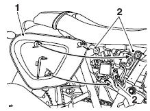
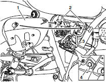
Street Scrambler
Left Hand Side Panel
The left hand side panel can be removed to gain access to the adjustment tool.
- Side panel (left hand shown)
- Grommets
To remove the left hand side panel: Grasp the panel firmly and pull the panel away from the motorcycle until it is free from the three retaining grommets (leaving the grommets in place).
To refit the left hand side panel: Position the three locating dowels to the grommets, then press firmly to secure the panel.
Finally, grasp the panel and make sure that it is fully retained.
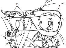
Right Hand Side Panel
The right hand side panel can be removed to gain access to the rear brake fluid reservoir.
- Side panel (right hand shown)
- Upper grommets
- Lower grommets
- Side panel attached to lower grommet
Note:
The exhaust system is shown removed for clarity.
To remove the right hand side panel: Grasp the panel firmly at the top and pull the panel away from the motorcycle until it is free from the two top retaining grommets, leaving the grommets in place.
Lift up the panel to detach it from the lower grommet.
To refit the right hand side panel: Position the side panel on to the lower grommet.
Make sure that the slot in the panel is fully engaged with the lower grommet.
Position the two locating dowels to the upper grommets, then press firmly to secure the panel.
Finally, grasp the panel and make sure that it is fully retained.
Tool Kit and Owner's Handbook
Tool Kit
The tool kit consists of an adjustment tool.
- Adjustment tool
Street Twin, Street Cup, Thruxton, Thruxton R, Bonneville T120 and Bonneville T100
The adjustment tool is attached to the inside of the right hand side panel.
Street Scrambler
The adjustment tool is attached to the inside of the left hand side panel.
Thruxton R
There are two C-spanners located under the seat.
Owner's Handbook
To gain access to the Owner's Handbook, remove the seat
Street Twin and Street Cup
The Owner's Handbook is located on the underside of the seat.
Street Scrambler
The Owner's Handbook is supplied separately.
Thruxton, Thruxton R, Bonneville T100 and Bonneville T120
The Owner's Handbook is located under the seat on the rear mudguard.
Helmet Hook
Note:
Not fitted on Thruxton, Thruxton R and Street Scrambler.
Warning
Never ride the motorcycle with helmet(s) secured to the helmet hook as this may cause the motorcycle to become unstable leading to loss of control and an accident.
Caution
Do not allow helmet(s) to rest against a hot silencer. The helmet may be damaged.
A helmet can be secured to the motorcycle using the helmet hook located on the left hand side of the motorcycle, beneath the seat.
To attach a helmet to the motorcycle, remove the seat and loop the helmet chin strap over the hook.
Make sure the flat area above the hook is not obstructed by the helmet strap, as this will prevent the seat engaging correctly.
To secure the helmet, refit the seat and lock into position.
Seats
Seat Care
Caution
To prevent damage to the seats or seat covers, care must be taken not to drop the seats.
Do not lean the seats against the motorcycle or any surface which may damage the seats or seat covers.
Instead, place the seats, with the seat cover facing upwards, on a clean, flat surface which is covered with a soft cloth.
Do not place any item on the seats which may cause damage or staining to the seat covers.
Thruxton and Thruxton R
Seat Stand
To prevent damage to the seat after removing: Release the metal stand from the underside of the seat.
Place the seat cover facing upwards, on a clean, flat surface using the metal stand and two plastic stands at the rear of the seat to rest on.
Seat Lock
Warning
To prevent detachment of the seat during riding, after fitting always grasp the seat and pull firmly upwards.
If the seat is not correctly secured in the lock, it will detach from the lock.
A loose or detached seat could cause loss of motorcycle control and an accident.
- Seat lock
The seat can be removed to gain access to the battery, fuse box (on certain models) and Owner's Handbook.
The seat lock is located on the left hand side of the motorcycle, on the frame below the seat.
Seat Removal and Installation
Warning
To prevent detachment of a seat during riding, after fitting always grasp the seat and pull firmly upwards.
If the seat is not correctly secured it will detach from the lock.
A loose or detached seat could cause loss of motorcycle control and an accident.
Street Twin, Street Cup, Thruxton, Thruxton R, Bonneville T100 and Bonneville T120
Seat Removal
To remove the seat:
- Seat lock
Insert the ignition key into the seat lock and turn it anticlockwise.
This will release the seat from its lock.
Slide the seat upwards and rearwards for complete removal from the motorcycle.
Street Twin, Street Cup, Thruxton, Thruxton R, Bonneville T100 and Bonneville T120
Seat Installation
To refit the seat: Engage the seat's tongue underneath the bracket near the fuel tank.
Line up the hinges and press down at the rear to engage the seat lock.
Note:
An audible click can be heard when the seat is fully engaged into its lock.
Street Scrambler Seat Removal
Note:
- If a passenger seat is fitted, it must be removed before removing the rider's seat.
- If a luggage rack is fitted, the rider's seat can be removed without removing the luggage rack.
Passenger Seat Removal
To remove the passenger seat:
- Passenger seat
- Fixing
Remove the fixing securing the passenger seat to the luggage rack frame.
Lift the seat up from the back and slide rearwards to remove it from the motorcycle.
Rider's Seat Removal
To remove the rider's seat: Remove the passenger seat if fitted.
- Seat lock
Insert the ignition key into the seat lock and turn it anticlockwise while pressing down on the rear of the seat.
This will release the seat from its lock.
Lift the seat up from the back and slide rearwards to remove it from the motorcycle.
Street Scrambler Seat Installation
Warning
To prevent detachment of a seat during riding, after fitting always grasp the seat and pull firmly upwards. If the seat is not correctly secured it will detach from the lock.
If the seat is not correctly secured it will detach from the lock.
A loose or detached seat could cause loss of motorcycle control and an accident.
Rider's Seat Installation
To install the rider's seat: Engage the seat's tongue under the fuel tank.
Note:
An audible click can be heard when the seat is correctly engaged in the lock.
Press firmly down in the centre of the seat to engage the lock.
Grasp the seat and make sure it is securely retained.
Passenger Seat Installation
To install the passenger seat: Make sure that the rider's seat is correctly fitted.
Align the front locating lugs on the passenger seat to their locating slots on the luggage rack subframe.
Gently push the seat forward until the rear locating lug fits into its hole on the luggage rack subframe.
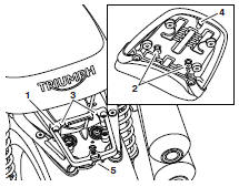
- Luggage rack subframe
- Front locating lugs
- Front locating lug slots
- Rear locating lug
- Rear locating lug hole
Secure the seat with its fixing and tighten to 3 Nm.
- Passenger seat
- Fixing
Grasp the seat and make sure that it is securely retained.
Universal Serial Bus (USB) Socket
Warning
The USB socket is not waterproof unless the waterproof cap is installed.
Do not connect electronic devices whilst it is raining.
Water in the USB socket could lead to an electrical problem, resulting in motorcycle damage, loss of motorcycle control and an accident.
Caution
Do not leave the ignition switch in the ON position unless the engine is running as this will discharge the battery.
Make sure that all electronic devices and cables are safely secured under the seat when riding.
Make sure there is sufficient space surrounding any electronic devices for the seat to close without causing any damage to the electronic device or the motorcycle.
USB Port Socket
The Universal Serial Bus (USB) socket allows a 5 Volt USB connection for charging electronic devices such as mobile phones, cameras and GPS devices.
Loads up to two Amps can be connected to the USB socket.
To access the USB socket, remove the seat
The USB socket is located on top of the battery.
Remove the cap.
Plug the relevant USB adaptor cable into the socket. Adaptor cables are not supplied with the motorcycle.
Running-In
 Running-in is the
name given to the
process that occurs during the first
hours of a new vehicle's operation.
Running-in is the
name given to the
process that occurs during the first
hours of a new vehicle's operation.
In particular, internal friction in the engine will be higher when components are new. Later on, when continued operation of the engine has ensured that the components have 'bedded in', this internal friction will be greatly reduced.
A period of careful running-in will ensure lower exhaust emissions, and will optimise performance, fuel economy and longevity of the engine and other motorcycle components.
During the first 500 miles (800 km):
- Do not use full throttle;
- Avoid high engine speeds at all times;
- Avoid riding at one constant engine speed, whether fast or slow, for a long period of time;
- Avoid aggressive starts, stops, and rapid accelerations, except in an emergency;
- Do not ride at speeds greater than 3/4 of maximum speed.
From 500 to 1,000 miles (800 to 1,500 km):
- Engine speed can gradually be increased to the rev limit for short periods.
Both during and after running-in has been completed:
- Do not overrev the engine when cold;
- Do not let the engine labour.
Always downshift before the engine begins to 'struggle';
- Do not ride with engine speeds unnecessarily high. Changing up a gear helps reduce fuel consumption, reduces noise and helps to protect the environment.
Daily Safety Checks
 Warning
Failure to perform these checks every day before you ride may result in serious motorcycle damage or an accident causing serious injury or death.
Check the following items each day before you ride. The time required is minimal, and these checks will help ensure a safe, reliable ride.
If any irregularities are found during these checks, refer to the Maintenance and Adjustment section or see your authorised Triumph dealer for the action required to return the motorcycle to a safe operating condition.
Check:
Fuel: Adequate supply in tank, no fuel leaks
Engine Oil: Correct level on dipstick or shown in sight glass. Add correct specification oil as required. No leaks from the engine or oil cooler
Drive Chain: Correct adjustment
Tyres/Wheels: Correct inflation pressures (when cold). Tread depth/ wear, tyre/wheel damage, loose/broken spokes, punctures etc.
Nuts, Bolts, Fasteners: Visually check that steering and suspension components, axles, and all controls are properly tightened or fastened. Inspect all areas for loose/damaged fixings.
Steering Action: Smooth but not loose from lock to lock. No binding of any of the control cables
Brakes: Pull the brake lever and push the brake pedal to check for correct resistance. Investigate any lever/pedal where the travel is excessive before meeting resistance, or if either control feels spongy in operation
Brake Pads: Check that the correct amount of friction material is remaining on all the brake pads
Brake Fluid Levels: No brake fluid leakage. Brake fluid levels must be between the MAX and MIN marks on both reservoirs
Front Forks: Smooth action. No fork oil leakage
Throttle: Make sure that the throttle grip returns to the idle position without sticking
Clutch: Smooth operation and correct cable free play
Coolant: No coolant leakage. Check the coolant level in the expansion tank (when the engine is cold)
Electrical Equipment: All lights and horn function correctly
Engine Stop: Engine start/stop switch turns the engine OFF when the switch is moved to the STOP position
Stands: Returns to the fully up position by spring tension. Return springs not weak or damaged
See also:
 Triumph Street Scrambler - Owner's Manual > Riding Modes
Note: Riding modes are available on the Thruxton, Thruxton R and Bonneville T120 models. The riding mode system allows adjustment of the throttle response.
Triumph Street Scrambler - Owner's Manual > How to Ride the Motorcycle
How to Ride the Motorcycle STOP position RUN position START position Ignition switch ON position Neutral indicator light (Street Twin and Street Scrambler only) Neutral indicator light (all other models)
 Ducati Scrambler
 Fantic Caballero 500
 Indian FTR 1200
 Moto Guzzi V85 TT
 Royal Enfield Bullet Trials Works Replica
 Triumph Scrambler 1200 XE
 Triumph Street Scrambler
 Yamaha XSR700
 Ducati Scrambler 800
 Moto Guzzi V85 TT
 Triumph Scrambler 1200 XC