 Ducati Scrambler 800 - Service manual > Overhauling the cylinder head components
Overhauling the heads
Remove any carbon deposits from the combustion chamber and its ducts.
Check for cracking and inspect the sealing surfaces for scoring, steps or other damage.
Make sure the coupling surface with the cylinder must be perfectly flat. If this is not the case, spread diamond lapping paste (6 Ă· 12 micron thickness) on a reference surface and slide the cylinder head with circular movements on the surface until a flat surface is obtained.
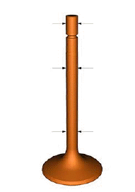
Checking the valves
Check that the stem and the valve seat contact surface are in good condition.
There must be no pitting, cracks, deformations or signs of wear.
Warning The valves cannot be ground.
Perform the following checks: measure the diameter of the valve stem at various points along the section that runs in the valve guide.
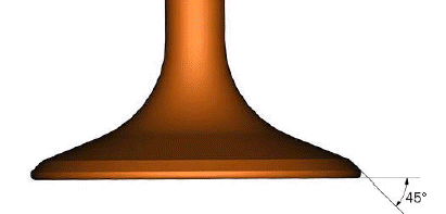
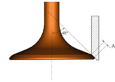
Check the valve stem for buckling. Place the valve on a "V" reference block, set a dial gauge perpendicular to head and measure concentricity of valve face at 45Âş:
- Service level: 0.03 mm
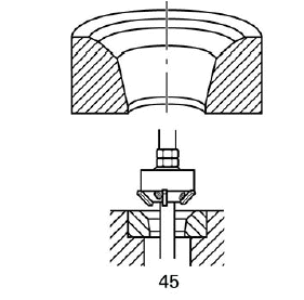
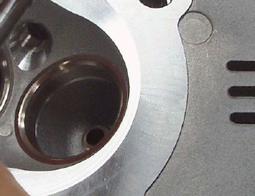
Checking the valve seats
Visually check the seats: they do not have to be excessively recessed or feature pitting or cracks.
In case the seat is slightly damaged, grind it using suitable 45Âş grinders and then lap the valves and check for any leakage. If the valve seats are excessively damaged, fit oversize seats. Spare seats are available with 0.03 and 0.06 mm oversized outside diameters.
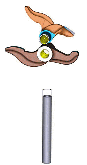
Valve guide
Check the internal surface of the valve guides: there should be no signs of deformation or cracking.
Thoroughly check the dimensions of the valve guide.
Measure the inside diameter with a suitable gauge.
Measure the diameter at different positions of the valve guide.
Check the diameter of head housings and choose the oversized valve seat that will give an interference fit of 0.11Ă·0.16 mm.
The valve seats are available as spare parts with outer diameter oversized by 0.03 and 0.06 mm.
Heat the cylinder head gradually and evenly to 200 ÂşC and chill the valve seats in dry ice.
Drive the seats keeping perfectly square in their housing using the suitable drift.
Leave them cool down and grind them, the union of the ducts with the new seats and lap the valves.
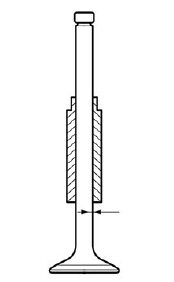
Coupling valve seat and valve
Use Prussian blue or a mixture of minium and oil to check that the contact surface (A) between valve and seat is 1.0Ă·1.5 mm.
Maximum allowed limit: 2.0 mm.
Grind the seat if the dimension measured is greater than the above limit.
Fill the fuel intake and discharge ducts to check for any leakage; in case of leakage, check that there are no burrs on the concerned seal surface.
Checking the valve - valve guide coupling
Clearance upon fitting: 0.03Ă·0.06 mm.
Maximum allowed wear limit: 0.08 mm.
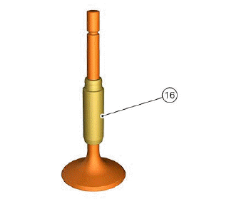
Replacing the valve guide
To replace the guide valve (16) it is necessary to perform the following operations.
Heat up the cylinder head gradually and evenly in an oven up to 200 ÂşC.
Slide out the valve guide using a suitable drift.
Leave it cool and check the seat conditions and dimensions.
Choose a suitable valve guide to obtain an interference fit in the cylinder head of 0.022Ă·0.051 mm; they are available as spare parts with outer diameter oversized by 0.03, 0.06 and 0.09 mm provided with stop ring.
Heat up the cylinder head again and chill the new valve guide in dry ice.
Install the valve guides after lubricating their seat, bring the stop ring fully home in the cylinder head using the drift suitable for its removal.
Leave the cylinder head cool and bore the internal hole.
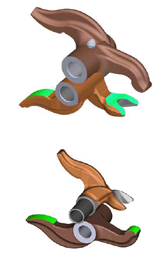
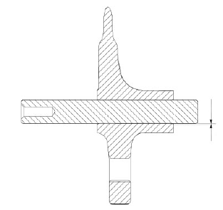
Overhauling the rocker arms
Check for signs of wear, grooves or chrome flaking off.
Check the conditions and the diameter of rocker arm bore and shaft:
- rocker arm internal hole nominal diameter: 10.040Ă·10.062 mm;
- shaft nominal diameter: 10Ă·0.005 mm.
Check that the work surfaces of the adjusters and the valve return shim caps are perfectly flat and do not feature wear signs.
Rocker arm-rocker arm shaft coupling
The clearance upon fitting must be 0.03Ă·0.06 mm.
Maximum allowed wear limit: 0.08 mm.
The rocker arms must be slightly forced on the cylinder head.
If the clearance is excessive, fit the shafts oversized by 0.02 mm.
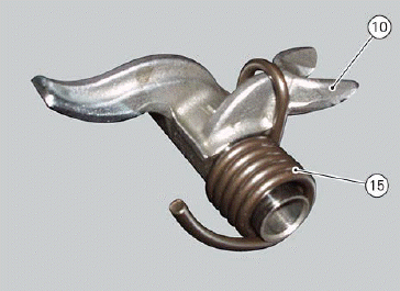
Checking the rocker arm springs
Thoroughly check the springs (15) of the closing rocker arms (10).
No cracks, deformations or failure must be present.
See also:
 Ducati Scrambler 800 - Service manual > Refitting the cylinder heads
Warning To prevent oil leaks in the contact area between cylinders and crankcase, each time the head is removed, cylinder and piston must be removed as well to clean the mating surfaces of crankcase and cylinder and restore the worn gaskets and O-rings and apply again sealing compound.
Ducati Scrambler 800 - Service manual > Removing the valves and rocker arms
Remove the valve covers, the camshafts and the relevant caps (Removing the camshafts). Slide out spring (4) of the opening rocker arm (5). Move rocker arm (5) to free the opening shim (6).
 Ducati Scrambler
 Fantic Caballero 500
 Indian FTR 1200
 Moto Guzzi V85 TT
 Royal Enfield Bullet Trials Works Replica
 Triumph Scrambler 1200 XE
 Triumph Street Scrambler
 Yamaha XSR700
 Ducati Scrambler 800
 Moto Guzzi V85 TT
 Triumph Scrambler 1200 XC