 Triumph Scrambler 1200 XC - Service manual > Scheduled Maintenance
WARNING
Triumph Motorcycles cannot accept any responsibility for damage or injury resulting from incorrect maintenance or improper adjustment carried out by the owner.
Incorrect or neglected maintenance can lead to a dangerous riding condition.
WARNING
Always have an authorised Triumph dealer carry out the scheduled maintenance of this motorcycle.
WARNING
All maintenance is vitally important and must not be neglected. Incorrect maintenance or adjustment may cause one or more parts of the motorcycle to malfunction. A malfunctioning motorcycle may lead to loss of control and an accident.
Weather, terrain and geographical location affect maintenance. The maintenance schedule should be adjusted to match the particular environment in which the motorcycle is used and the demands of the individual owner.
Special tools, knowledge and training are required in order to correctly carry out the maintenance items listed in the scheduled maintenance chart. Only an authorised Triumph dealer will have this knowledge and equipment.
Incorrect or neglected maintenance can lead to a dangerous riding condition.
Always have an authorised Triumph dealer carry out the scheduled maintenance of this motorcycle.
To maintain the motorcycle in a safe and reliable condition, the maintenance and adjustments outlined in this section must be carried out as specified in the schedule of daily checks, and also in line with the scheduled maintenance chart. The information that follows describes the procedures to follow when carrying out the daily checks and some simple maintenance and adjustment items.
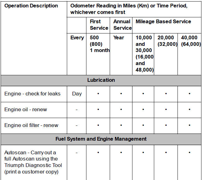
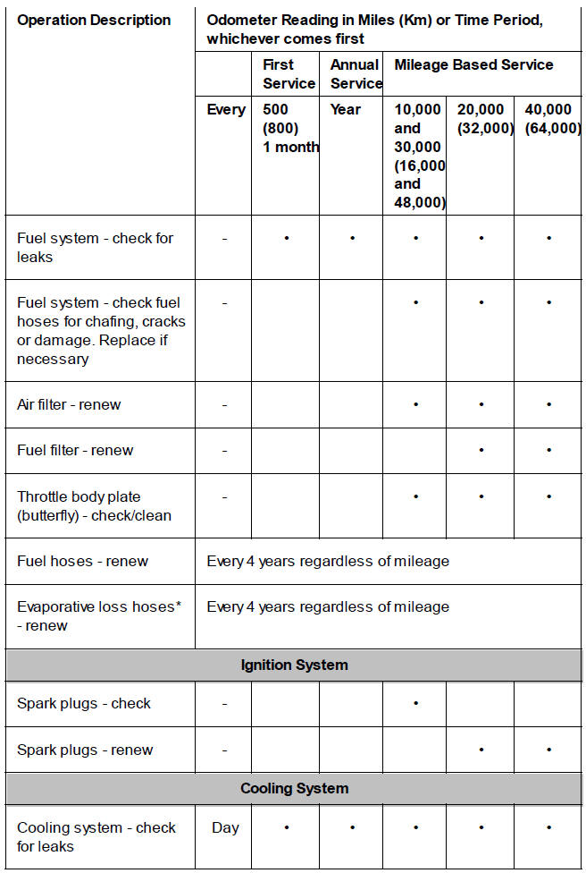
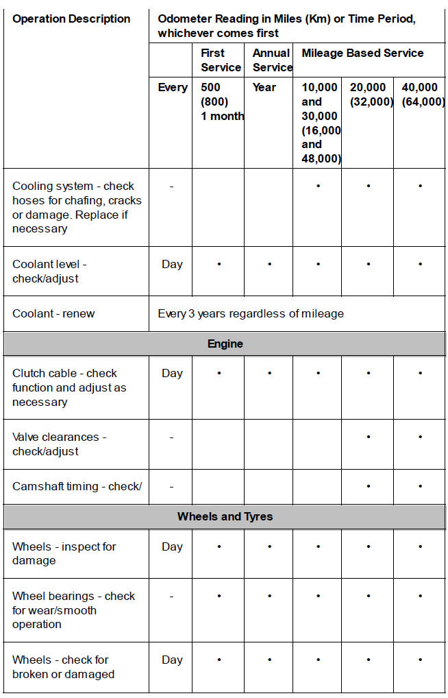
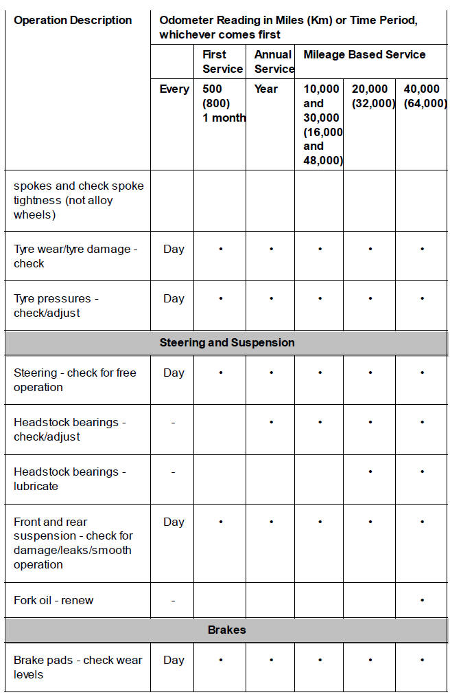
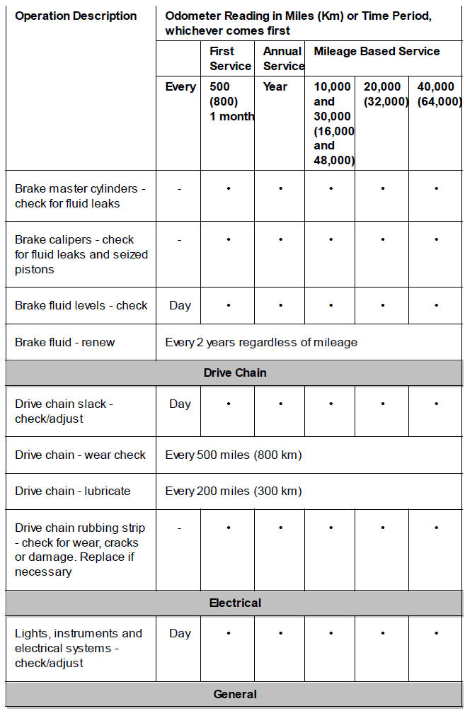
Scheduled maintenance may be carried out by your authorised Triumph dealer in three ways; annual maintenance, mileage based maintenance or a combination of both, depending on the mileage the motorcycle travels each year.
- Motorcycles travelling less than 10,000 miles (16,000 km) per year must be maintained annually. In addition to this, mileage based items require maintenance at their specified intervals, as the motorcycle reaches this mileage.
- Motorcycles travelling approximately 10,000 miles (16,000 km) per year must have the annual maintenance and the specified mileage based items carried out together.
- Motorcycles travelling more than 10,000 miles (16,000 km) per year must have the mileage based items maintained as the motorcycle reaches the specified mileage. In addition to this, annual based items will require maintenance at their specified annual intervals.
In all cases maintenance must be carried out at or before the specified maintenance intervals shown. Consult an authorised Triumph dealer for advice on which maintenance schedule is most suitable for your motorcycle.
Triumph Motorcycles cannot accept any responsibility for damage or injury resulting from incorrect maintenance or improper adjustment.
Service Symbol/General Warning Symbol
 The service symbol will
illuminate for five seconds after the motorcycle start up
sequence as a reminder that a service is due in approximately 60 miles (100 km).
The service symbol will
illuminate for five seconds after the motorcycle start up
sequence as a reminder that a service is due in approximately 60 miles (100 km).
The service symbol will illuminate permanently when the mileage is reached, it will remain permanently illuminated until the service interval is reset using the Triumph Diagnostic tool.
 The general warning symbol will
flash if an ABS or engine management fault has
occurred and the ABS and/or MIL warning lights are illuminated. Contact an
authorised Triumph dealer as soon as possible to have the fault checked and
rectified.
The general warning symbol will
flash if an ABS or engine management fault has
occurred and the ABS and/or MIL warning lights are illuminated. Contact an
authorised Triumph dealer as soon as possible to have the fault checked and
rectified.
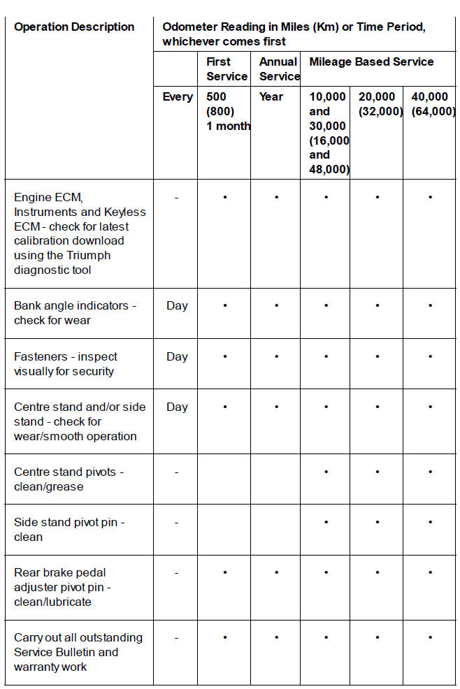
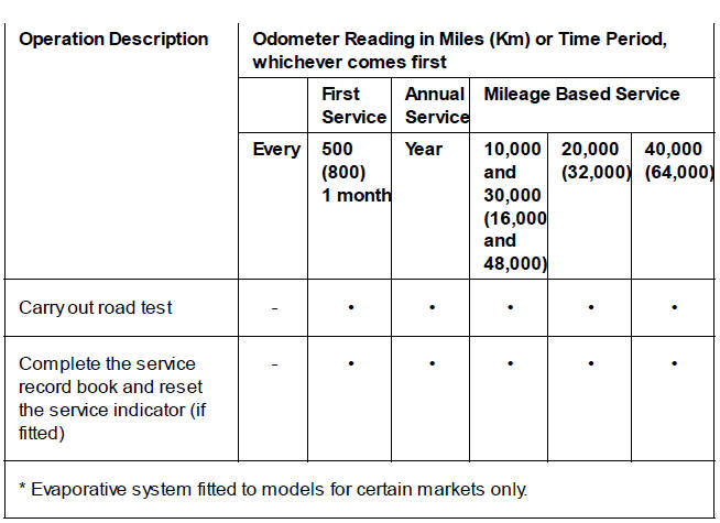
Scheduled Maintenance Table
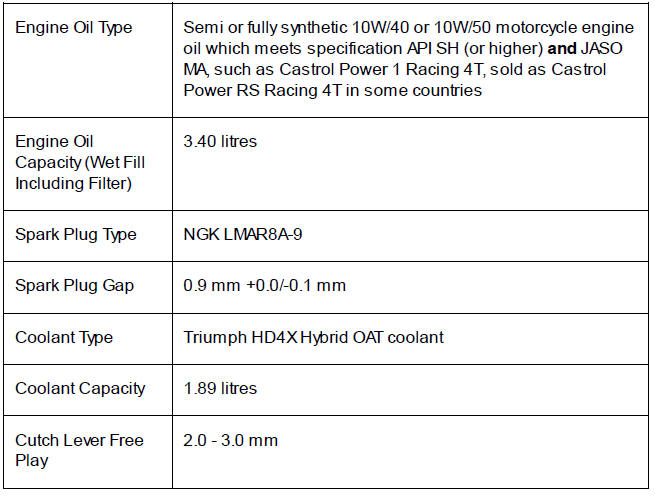
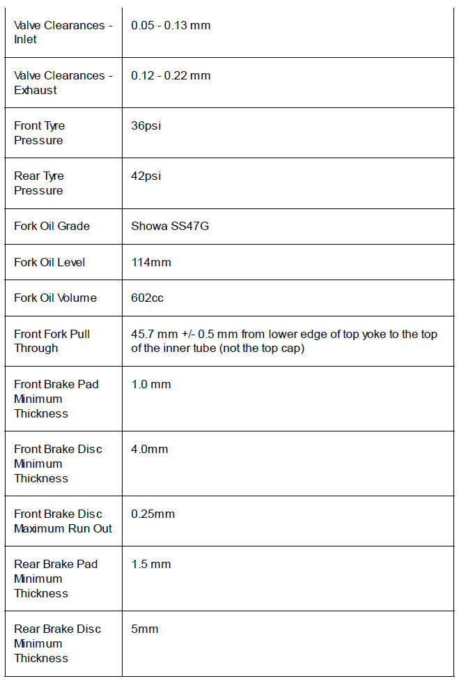
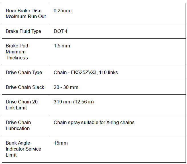
Service Specifications
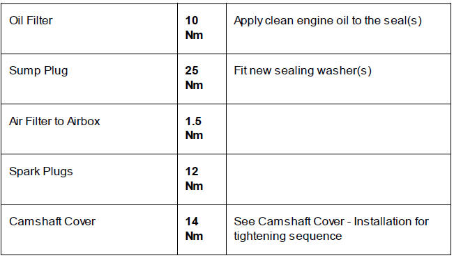
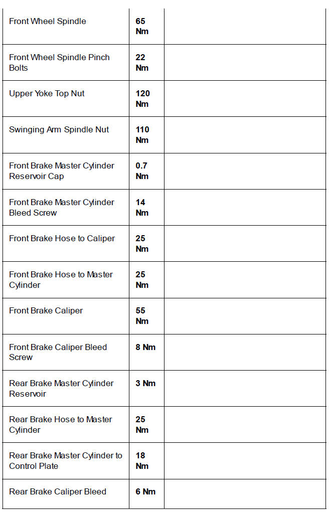
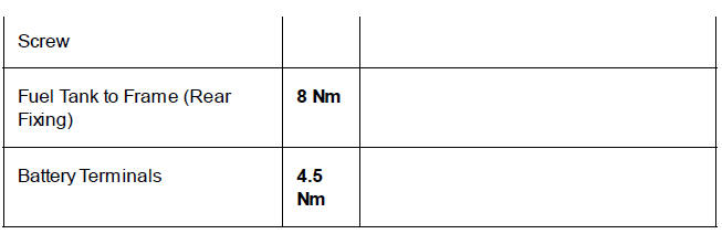
Service Torque Wrench Settings
Routine Maintenance
Perform the following operations:
- Seat - Removal
- Battery - Removal
- Remove both front forks (see Front Fork - Removal).
- Remove the upper yoke (see Upper Yoke - Removal).
1. Disconnect the electrical connectors for the front indicators from the main harness.
2. Release the fixings and remove theheadlight brackets.
3. Remove the fixings and release the brake hose assembly from the lower yoke.
- Headlight brackets
- Headlight bracket fixings
- Brake hose fixings
- Brake hose assembly
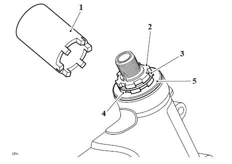
4. UseT3880023 - 50 mm Socket to remove the lock nut.
5. Remove the tab washer, then use T3880023 - 50 mm Socket again to remove the adjuster nut.
6. Remove the bearing cover and dust seal.
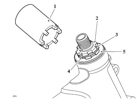
- T3880023 - 50 mm Socket
- Lock nut
- Tab washer
- Adjuster nut
- Bearing cover and dust seal
7. Remove the lower yoke from below the frame headstock.
WARNING
Always wear eye, hand and face protection when using a hammer and drift. Use of a hammer and drift can cause bearings to fragment. Pieces of fragmented bearing could cause eye and soft tissue injuries if suitable protective apparel is not worn.
8. Using a suitable drift, evenly and progressively drive the bearing races from the frame headstock.
9. Remove the inner race and dust seal from the lower yoke using a press or puller.
WARNING
Before starting work, ensure the motorcycle is stabilised and adequately supported. This will help prevent it from falling and causing injury to the operator or damage to the motorcycle.
1. Raise and support the motorcycle so that the rear wheel is clear of the ground.
Note
If both suspension units are to be removed, place a block beneath the rear wheel to prevent it dropping when the second unit is removed.
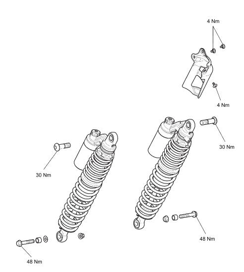
2. Loosen and remove the lower mounting nut, sleeve and bolt. Discard the nut.
3. Loosen and remove the upper bolt and remove the suspension unit. Discard the bolt.
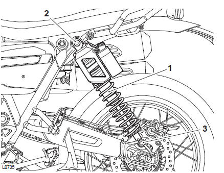
- Rear suspension unit
- Upper mounting bolt
- Lower mounting nut and bolt
4. Repeat steps 2 and 3 for the other rear suspension unit (if required).
1. Fit a new dust seal to the steering stem on the lower yoke as noted for removal.
CAUTION
Protect the threads of the lower yoke when using a press or a puller as damaged threads may mean replacing the lower yoke completely.
2. Press a new lower bearing inner race onto the steering stem of the lower yoke.
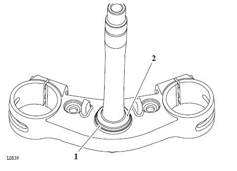
- Dust seal
- Bearing inner race
3. Evenly and progressively drive the new upper and lower bearing outer races into the frame headstock.
- Headstock
4. Lubricate the headstock bearings using Castrol LCX 222 or an equivalent heavy duty lithium based grease.
5. Fit the bearing to the bearing inner race on the steering stem.
6. Insert the lower yoke to the frame headstock, fit the upper bearing, inner race, dust seal and retain with the adjuster nut.
7.Adjust the bearing free play as follows:
- Remove the adjuster nut.
- Thoroughly clean the threads on the steering stem.
- Refit the adjuster nut and use T3880023 - 50 mm Socket to torque the adjuster nut to 40 Nm.
- Loosen the adjuster nut, then retighten to 15 Nm.
- Fit the tab washer and lock nut.
- Torque the lock nut to 40 Nm.
WARNING
It is essential that the adjuster nut is not overtightened. If the adjuster is overtightened it will cause a preload on the headstock bearings. This will introduce tight steering, which could cause loss of motorcycle control and an accident.
Note
Ensure the adjuster nut does not move as the lock nut is tightened.
- T3880023 - 50 mm Socket
- Lock nut
- Tab washer
- Adjuster nut
- Dust seal
8. Fit the headlight brackets to the lower yoke and tighten the fixings to 3 Nm.
9. Connect the electrical connectors for the front indicators.
Perform the following operations:
- Upper Yoke - Installation
- Linked procedure not present at the moment.
- Battery - Installation
- Seat - Installation
WARNING
Operation of the motorcycle with incorrectly adjusted steering head bearings, either too loose or too tight, may cause a dangerous riding condition leading to loss of motorcycle control and an accident.
- Check and if necessary correct the headlight adjustment (see Headlight Vertical Adjustment).
- Check that the free play has been eliminated and that the steering can be turned freely from lock-to-lock without any sign of tightness. Readjust if necessary
WARNING
Before starting work, ensure the motorcycle is stabilised and adequately supported. This will help prevent it from falling and causing injury to the operator or damage to the motorcycle.
Perform the following operations:
- Seat - Removal
- Battery - Removal
- Mirrors - Removal
- Twist Grip - Removal
1. Remove the fixings for the mirror brackets and release the brackets.
2. If a non-heated left handgrip is installed, remove the top and bottom fixings and remove the grip.
- Fixing
- Grip
3. Release the fixing and detach the clutch switch and switch cover from the clutch lever assembly.
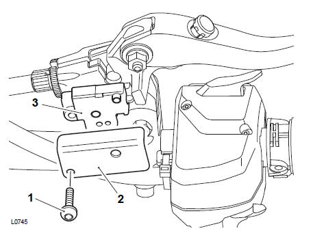
- Fixing
- Switch cover
- Clutch switch
4. Release the fixings and remove the clamp from the clutch lever assembly.
Without disconnecting the clutch cable, lay the lever aside.
5. Remove the cable tie securing the switch housing wiring harness to the left hand switch housing.
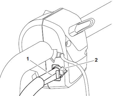
- Wiring harness
- Cable tie
6. Gently pull on the wiring harness to disconnect the switch housing connectors.
- Switch housing connectors
WARNING
The T3880369 - Switch Housing Removal Tool is required to release the handlebar switch housings from their retaining clips.
When inserting T3880369 - Switch Housing Removal Tool into the switch housing, a click can be felt/heard as the retaining clip is released.
The retaining clip will remain in position on the handle bar as the switch housing is removed. Note the position and orientation of the clip for installation.
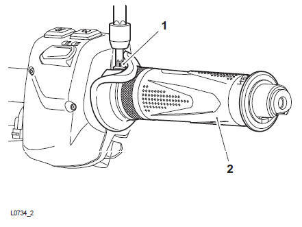
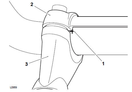
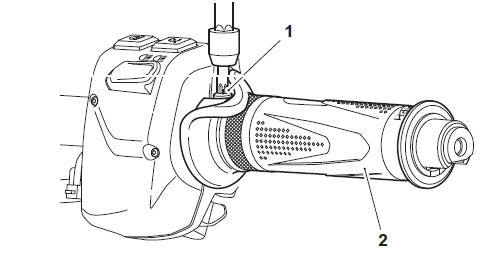
7. Insert T3880369 - Switch Housing Removal Tool into the opening on the left hand switch housing until a click is felt/heard.
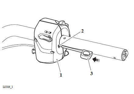
1. Left hand switch housing 2. Opening 3. T3880369 - Switch Housing Removal Tool
8. Slide the switch housing towards the end of the handlebar to free it from the retaining clip.
9. Withdraw T3880369 - Switch Housing Removal Tool from the switch housing.
- Left hand switch housing
- T3880369 - Switch Housing Removal Tool
- Retaining clip
10. Slide the switch housing off the handlebar and collect the retaining clip.
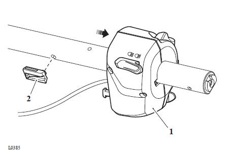
- Switch housing
- Retaining clip
11. Disconnect and remove the right hand switch housing as described in steps 4-9.
12. Release the fixings and remove the clamp from the front brake master cylinder.
Taking care to not invert the brake fluid reservoir, lay the assembly aside.
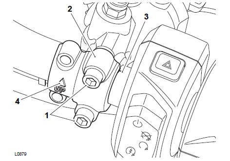
- Fixings
- Clamp
- Alignment mark
- "UP" Arrow
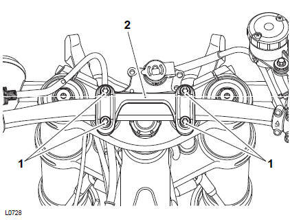
13. With the aid of an assistant, support the handlebar and release the fixings securing the handlebar clamp to the risers. Remove the handlebar clamp.
- Fixings
- Handlebar clamp
14. Slide the twist grip position sensor off the handle bar. Without disconnecting any wiring, lay the sensor aside.
15. Disconnect and remove the right hand switch housing as described in steps 3 to 8.
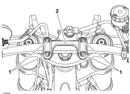
1. If removed, put the two handlebar risers and spacers (if installed) in position.
Install the fixings that attach the two handlebar risers and torque the fixings to 38 Nm.
2.
Refit the upper yoke. Make sure that the two pins on the underside of the upper yoke are engaged into the grommets for the headlight bracket.
- Handlebar risers
- Riser fixings
- Grommets
- Headlight brackets
- Upper yoke
4. Fit and tighten the top nut to 120 Nm.
5. Tighten the upper yoke pinch bolts to 25 Nm.
6. Locate the handlebars onto the risers. Fit the clamp and the fixings but do not fully tighten at this stage.
7. Rotate the handlebar so that the alignment mark on the handlebar aligns with the bottom face of the handlebar clamp.
- Alignment mark
- Handlebar clamp
- Right riser
8. Tighten the handlebar clamp fixings, front ones first, to 24 Nm.
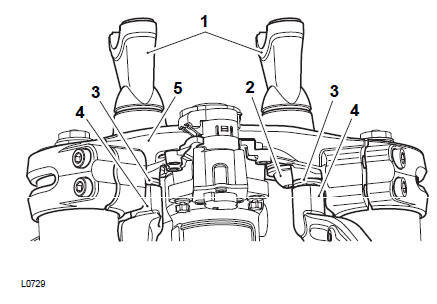
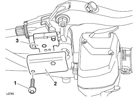
9. Put the instrument and bracket assembly in position.
10. Install three new fixings and torque to 5 Nm.
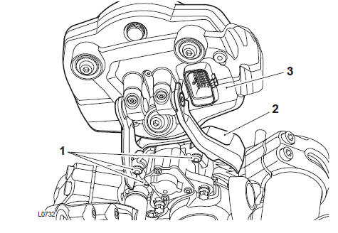
- Fixings
- Instrument bracket
- Instruments
11. Connect the electrical connector to the instruments.
12. Install the cover for the connector.
13. Install and torque the fixing for the cover to 3 Nm.
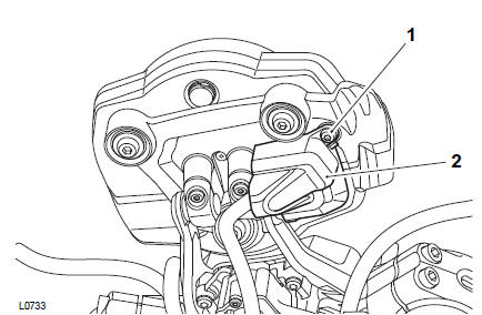
- Fixing
- Cover
Perform the following operations:
- Headlight - Installation
- Battery - Installation
- Seat - Installation
WARNING
Before starting work, ensure the motorcycle is stabilised and adequately supported. This will help prevent it from falling and causing injury to the operator or damage to the motorcycle.
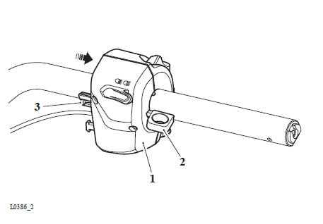
1. Fit the right hand switch housing retaining clip to the handlebar as noted during removal.
2. Slide the right hand switch housing onto the handlebar and over the retaining clip until it locks into position.
- Switch housing
- Retaining clip
3. Slide the twist grip position sensor onto the right hand side of the handlebar.
4. Locate the handlebar onto the risers, fit the clamp and the fixings. Do not fully tighten at this stage.
- Fixings
- Handlebar clamp
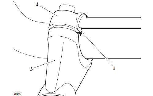
5. Position the handlebar so that the inside corner of the clamp is aligned with the alignment mark on the front of the handlebar, as shown below.
- Clamp
- Alignment mark
- Handlebar riser
6. Tighten the handlebar clamp fixings, front ones first, to 24 Nm 7. Connect the right hand switch housing electrical connectors.
8. Use a new cable tie to secure the wiring harness to the switch housing.
9. Do steps 1 and 2 again for the left switch housing.
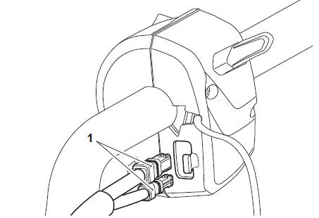
Note
- The left hand switch housing electrical connections are recessed into the switch housing body.
- To aid orientation, there are coloured dots on each connector. The coloured dots identify the bottom face of the connector.
- When inserting the connectors, carefully locate the connectors into their sockets, then use a suitable flat ended pin punch to push the connectors fully home. An audible click can be heard when the connectors are fully inserted.
- Do not use sharp tools, such as a flat bladed screw driver, to insert the connectors.
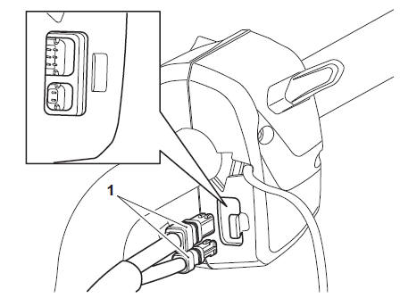
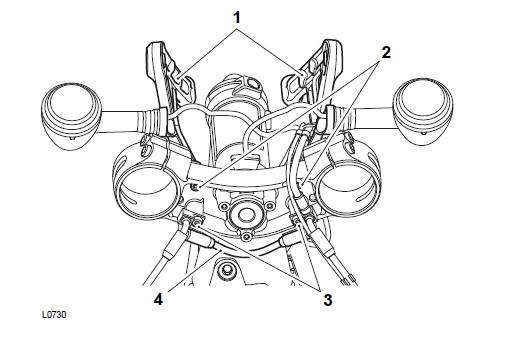
1. Switch housing electrical connectors
10. Connect the left hand switch housing electrical connectors.
11. Use a new cable tie to secure the wiring harness to the switch housing.
12. Locate the master cylinder to the handlebars and position the clamp with the UP arrow pointing upwards. Do not tighten the clamp bolts at this stage.
13. Align the split line of the master cylinder clamp to the alignment mark on the top surface of the handlebar. Tighten the clamp fixings, upper one first, to 8 Nm.
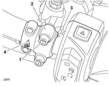
- Fixings
- Clamp
- Alignment mark
- "UP" Arrow
14. Position the clutch lever assembly to the handlebar.
15. Align the split line of the clutch lever clamp to the alignment mark on the top surface of the handlebar. Tighten the clamp fixings, upper one first, to 12 Nm.
16. Put the clutch switch and switch cover in position.
17. Install the fixing to attach the clutch switch and switch cover to the clutch lever assembly. Torque the fixing to 1 Nm
- Fixing
- Switch cover
- Clutch switch
18. If a non-heated left handgrip is installed, install the grip and tighten the top and bottom fixings to 2 Nm.
- Fixing
- Grip
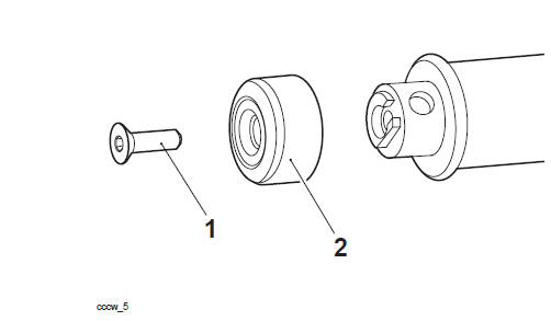
19. Install the left hand handlebar end weight and tighten the fixing to 5 Nm.
Position the two mirror brackets and tighten the fixings to 5 Nm.
Perform the following operations:
- Install the heated twist grip (see Twist Grip - Installation).
- Install the two mirrors (see Mirrors - Installation).
- Battery - Installation
- Seat - Installation
See also:
 Triumph Scrambler 1200 XC - Service manual > Engine Check For Fluid Leaks
WARNING Before starting work, ensure the motorcycle is stabilised and adequately supported. This will help prevent it from falling and causing injury to the operator or damage to the motorcycle.
 Ducati Scrambler
 Fantic Caballero 500
 Indian FTR 1200
 Moto Guzzi V85 TT
 Royal Enfield Bullet Trials Works Replica
 Triumph Scrambler 1200 XE
 Triumph Street Scrambler
 Yamaha XSR700
 Ducati Scrambler 800
 Moto Guzzi V85 TT
 Triumph Scrambler 1200 XC