 Triumph Scrambler 1200 XC - Service manual > Air Filter Element - Renew
WARNING
Before starting work, ensure the motorcycle is stabilised and adequately supported. This will help prevent it from falling and causing injury to the operator or damage to the motorcycle.
Perform the following operations:
- Remove the left hand Side Panels
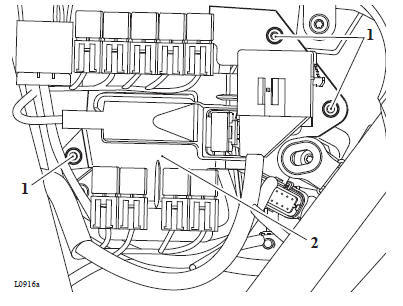
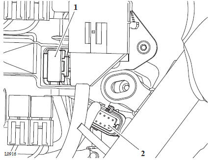
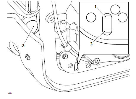
- Detach the main fuse and the keyless electronic control module (ECM) multiplug from the relay bracket.
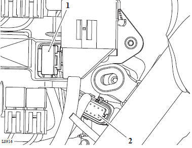
- Main fuse
- Keyless ECM multiplug
2. Remove the fixings and detach the relay bracket from the left hand side of the airbox.
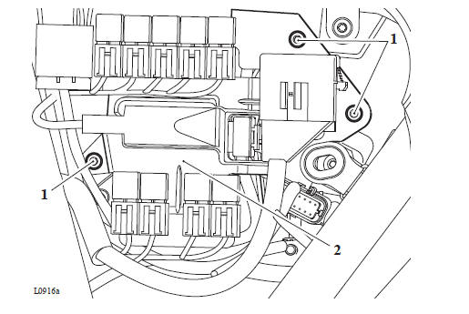
- Fixings
- Relay bracket
3. Release the four fixings securing the air filter cassette to the airbox and remove the air filter cassette.
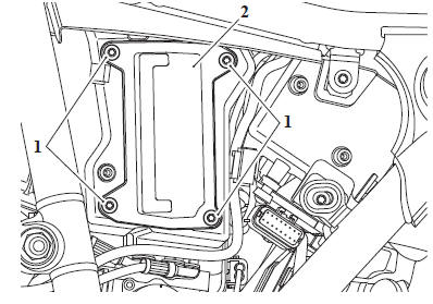
- Fixings
- Air filter cassette
4. Inspect the air filter cassette seal for damage, replace if necessary
Note
Note the orientation of the air filter element and air filter cassette for installation.
5. Remove the air filter cassette from the air filter.
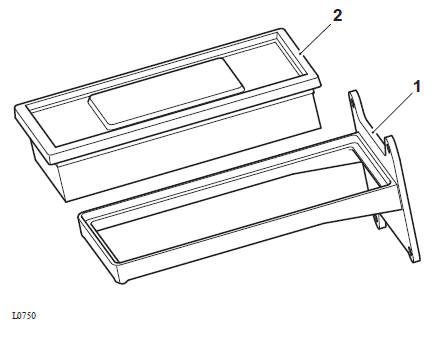
- Cassette
- Air filter element
Installation
1. Clean the air filter cassette and the interior of the airbox.
2. Locate the new air filter element into the air filter cassette, as noted for removal.
3. Fit the air filter and cassette assembly to the airbox and tighten its fixings to 1 Nm.
4. Attach the relay bracket to the airbox and tighten its fixings to 1.5 Nm.
- Fixings
- Relay bracket
5. Attach the main fuse and the keyless electronic control module (ECM) multiplug to the relay braket.
- Main fuse
- Keyless (ECM) multiplug
Perform the following operations:
- Refit the left hand Side Panels
Fuel Filter - Renew
Removal
WARNING
Before starting work, ensure the motorcycle is stabilised and adequately supported. This will help prevent it from falling and causing injury to the operator or damage to the motorcycle.
WARNING
Observe the warning advice given in the General Information section on the safe handling of fuel and fuel containers.
A fire, causing personal injury and damage to property could result from spilled fuel or fuel not handled or stored correctly.
Perform the following operations:
- Fuel Pump Assembly - Removal
1. Release the two fuel hose clips from either side of the fuel filter.
2. Remove the hose bracket from the fuel pump bracket.
- Hose clips
- Hose bracket
3. Carefully detach the baffle housing from the fuel pump.
- Baffle housing
- Hose clip
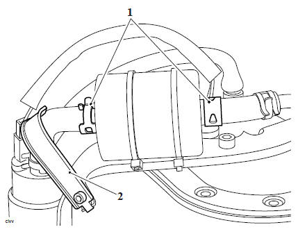
4. Remove the fuel pump securing bolt and strap.
- Strap
- Bolt
5. Disconnect the fuel pump hose from the fuel filter inlet.
6. Remove and discard the two fuel filter cable ties.
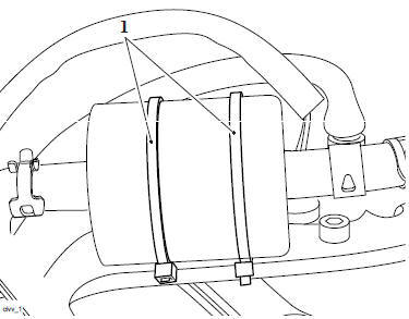
- Cable ties
Note
Prior to removing the filter, note the direction of the arrow on the side of the filter. The arrow should point away from the fuel pump, towards the pressure regulator.
7. Remove the fuel filter from the outlet hose.
Inspection
1. Inspect all hoses for cracks, splits, fraying and other damage. Replace as necessary.
2. Check all hose clamps for cracks and signs of distortion. Replace as necessary.
3. Check the mesh filter for damage and replace the fuel pump if necessary.
Installation
1. Install the fuel filter to the outlet hose, ensuring the arrow on the filter points away from the pump. Secure the hose with the hose clip.
2. Check and ensure that the feet of the rubber isolator engage correctly in the fork.
- Fork
- Isolator feet
3. Secure the fuel filter to the fuel pump bracket with two new cable ties.
4. Connect the fuel pump hose to the fuel filter and secure with the hose clip.
5. Refit the fuel pump securing bolt and strap and tighten the bolt to 4 Nm.
6. Refit the hose bracket to the fuel pump bracket and tighten its fixing to 7 Nm.
7. Carefully refit the baffle material into the front of the baffle housing.
8. Refit the baffle housing to the fuel pump as noted for removal.
Perform the following operations:
- Fuel Pump Assembly - Installation
Throttle Body Plate (butterfly) - check/clean
WARNING
Before starting work, ensure the motorcycle is stabilised and adequately supported. This will help prevent it from falling and causing injury to the operator or damage to the motorcycle.
Perform the following operations:
- Throttle Body and Inlet Manifold Assembly - Removal
- Using a lint free cloth and a suitable degreaser such as Castrol Motorcycle Parts Cleaner, remove any residue from the internal surfaces and throttle plate (butterfly).
- Check for any signs of damage and ensure the butterfly moves correctly.
Perform the following operations:
Throttle Body and Inlet Manifold Assembly - Installation
Fuel/Evaporative System - Check For Leaks, Routing, Chafing and Security
Standard required:
Fuel/evaporative hoses must be secure and routed in such a way that they do not chafe against moving parts of the motorcycle.
Fuel/evaporative hoses must not be routed around sharp curves. This could cause restrictions in the flow of fuel.
Fuel/evaporative system components must be free from damage.
The fuel tank cap must be easy to open and close.
The fuel tank cap seal must be free from damage.
The fuel cap lock barrel and key (if fitted) must operate easily and smoothly.
Check:
Visually check fuel/evaporative system components for signs of fuel leakage.
Visually check fuel/evaporative system components for signs of damage.
Visually check fuel/evaporative system components for security (where accessible).
Check the operation of the fuel filler cap and lock (if fitted).
Visually inspect the fuel cap seal for signs of damage.
Rectification if required:
Fuel/evaporative leaks must be rectified.
Damaged fuel/evaporative system components must be replaced.
An incorrectly fitting fuel cap must be replaced.
Autoscan
Actions required
Perform an Autoscan using the Triumph Diagnostic Software in accordance with the Triumph Diagnostic Tool User Guide.
Check
Check all results pass the Autoscan, and save the results.
Print a customer copy.
Spark Plugs
Spark Plugs - Check/Renew
WARNING
Before starting work, ensure the motorcycle is stabilised and adequately supported. This will help prevent it from falling and causing injury to the operator or damage to the motorcycle.
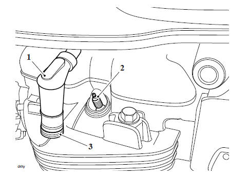
1. Detach the spark plug caps from the spark plugs.
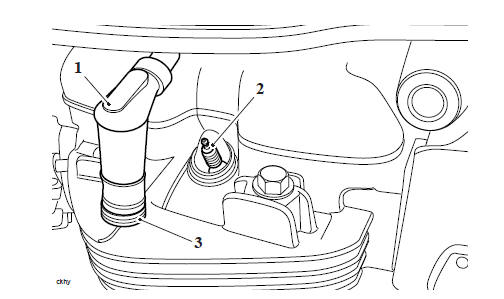
- Spark plug cap
- Spark plug
- Spark plug cap seal
2. Using a suitable tool remove the spark plugs from the cylinder head.
3.Check the condition of the spark plug cap seal for wear and/or damage. Replace as necessary.
4.Check for signs of abnormal discolouration or deposits (see Spark Plugs - Inspection).
5. Check and if necessary adjust the spark plug gap to 0.9 mm +0.0/-0.1 mm.
6. Refit the spark plugs or, if required, fit new spark plugs and tighten to 12 Nm.
- Spark plug cap
- Spark plug
- Spark plug cap seal
7. Refit the spark plug caps to the spark plugs.
Spark Plugs - Inspection
Assessing the condition of a spark plug can be a valuable aid to a technician, and a good source of information about the engines overall operating condition.
In general, a light brown/grey colour tells you that the spark plug is operating at optimum temperature and that the engine is in good condition.
Dark colouring, such as heavy wet or dry deposits, can indicate:
- an overly rich condition
- too cold a heat range spark plug
- a possible vacuum leak
- low compression
- overly retarded timing
- too large a spark plug gap.
If the deposits are wet, it can be an indication:
- of a breached head gasket
- poor oil control from the piston rings
- valve train problems
- an extremely rich condition - depending on the actual liquid present at the firing tip.
Signs of fouling or excessive heat must be traced quickly to prevent further deterioration of performance and possible engine damage.
Normal Condition
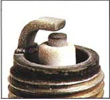
An engines condition can be judged by the appearance of the spark plugs firing end.
If the firing end of a spark plug is light brown or grey, the condition can be judged to be good and the spark plug is functioning optimally.
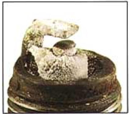
Dry and Wet Fouling
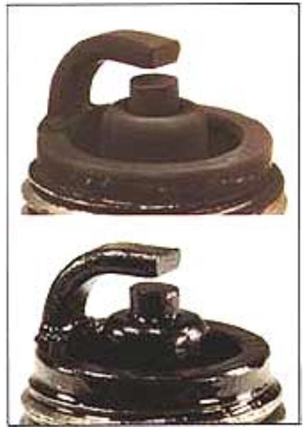
Although there are many different scenarios, if the insulation resistance between the centre electrode and the shell is over 10 Ohms, the engine can be started normally. If the insulation resistance drops to 0 Ohms, the firing end is fouled by either wet or dry carbon.
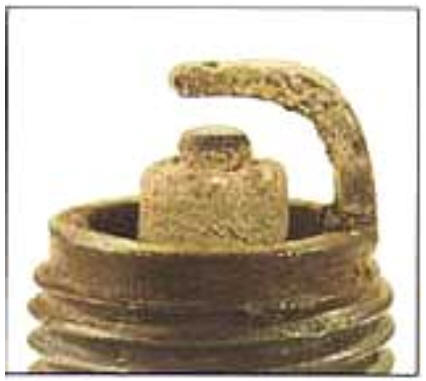
Overheating
When a spark plug overheats, deposits that have accumulated on the insulator tip melt and give the the insulator a glazed or glossy appearance.
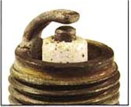
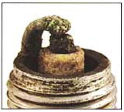
Deposits
The accumulation of deposits on the firing end is influenced by oil leakage, fuel quality and the engines operating duration.
Breakage

Breakage is usually caused by thermal expansion and thermal shock due to sudden heating or cooling.
Normal Life
A worn spark plug not only wastes fuel but also strains the whole ignition system because the expanded gap (due to erosion) requires higher voltages. Normal rates of gap growth are: 0.00063 - 0.000126 inches per 1000 miles (0.01 - 0.02 mm per 1000 km)
Melting
Melting is caused by overheating. Mostly, the electrode surface is rather lustrous and uneven. The melting point of nickel alloy is 1200 to 1300 ºC (2200 to 2400 ºF).
Erosion, Corrosion and Oxidation
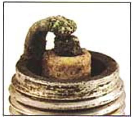
The material of the electrodes has oxidised, and when the oxidation is heavy, it will be green on the surface. The surface of the electrodes will also be fretted and rough.
Coolant Level
Coolant Level Adjustment
WARNING
Before starting work, ensure the motorcycle is stabilised and adequately supported. This will help prevent it from falling and causing injury to the operator or damage to the motorcycle.
WARNING
Do not remove the expansion tank or coolant pressure cap when the engine is hot. When the engine is hot, the coolant inside the cooling system will be hot and may also be under pressure. Contact with hot coolant will cause scalds and skin damage.
1. Allow the engine to cool for a minimum of 30 minutes.
2. Remove the sump guard (see Sump Guard - Removal).
Remove the cap from the expansion tank, and add coolant mixture through the filler opening until the level reaches the MAX mark. Refit the cap.
- Maximum level
- Minimum level
- Filler opening
4. Refit the sump guard (see Sump Guard - Installation).
Note
- If the coolant level is being checked because the coolant has overheated, also check the level in the radiator and top up if necessary.
- In an emergency, distilled water can be added to the cooling system. However, the coolant must then be drained and replenished with HD4X Hybrid OAT coolant as soon as possible.
Coolant Renew
WARNING
Before starting work, ensure the motorcycle is stabilised and adequately supported. This will help prevent it from falling and causing injury to the operator or damage to the motorcycle.
WARNING
Do not remove the expansion tank or coolant pressure cap when the engine is hot. When the engine is hot, the coolant inside the cooling system will be hot and may also be under pressure. Contact with hot coolant will cause scalds and skin damage.
1. Allow the engine to cool for a minimum of 30 minutes.
- Drain the coolant (see Coolant Replacement - Drainage).
- Refill the coolant with Triumph HD4X Hybrid OAT coolant (see Coolant Replacement - Filling).
See also:
 Triumph Scrambler 1200 XC - Service manual > Engine Check For Fluid Leaks
WARNING Before starting work, ensure the motorcycle is stabilised and adequately supported. This will help prevent it from falling and causing injury to the operator or damage to the motorcycle.
Triumph Scrambler 1200 XC - Service manual > Valve Clearance Adjustment
WARNING Before starting work, ensure the motorcycle is stabilised and adequately supported. This will help prevent it from falling and causing injury to the operator or damage to the motorcycle.
 Ducati Scrambler
 Fantic Caballero 500
 Indian FTR 1200
 Moto Guzzi V85 TT
 Royal Enfield Bullet Trials Works Replica
 Triumph Scrambler 1200 XE
 Triumph Street Scrambler
 Yamaha XSR700
 Ducati Scrambler 800
 Moto Guzzi V85 TT
 Triumph Scrambler 1200 XC