 Triumph Scrambler 1200 XC - Service manual > Balancer
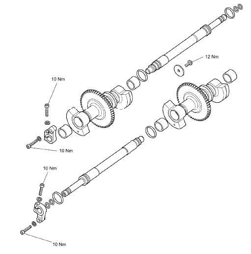
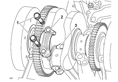
Exploded View - Balancers
Introduction
Two balancer shafts are fitted to the engine, one in front of the crankshaft in the upper crankcase and one behind it in the lower crankcase. Each balancer has the effect of a pair of counterbalance weights, which create an equal amount of energy in the opposite direction, and at the same time as that produced by the crankshaft, pistons and connecting rods. Because the opposing pulses occur at the same point of crankshaft rotation, and are of an equal magnitude, a state of equilibrium or balance is reached.
Rear Balancer Shaft - Removal
WARNING
Before starting work, ensure the motorcycle is stabilised and adequately supported. This will help prevent it from falling and causing injury to the operator or damage to the motorcycle.
Perform the following operations:
- Seat - Removal
- Battery - Removal
- Fuel Tank - Removal
- Engine - Removal
- Crankcase - Disassembly
1. Remove the input and output shafts.
Note
The rear dead shaft clamp is marked with the R facing away from the crankcase.
2. Loosen but do not fully remove the dead shaft clamp locking screw,
3. Remove the dead shaft clamp securing screw and washer. Discard the screw, retain the washer for reuse.
- Dead shaft clamp
- Locking screw
- Securing screw
- Washer
- Dead shaft
4. Release the dead shaft screw and washer. Discard the dead shaft screw and retain the washer.
- Screw
- Washer
- Dead shaft
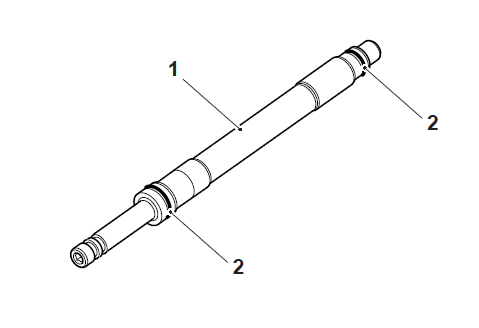
5. Support the balancer shaft and noting its orientation slide the dead shaft from the crankcase.
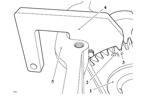
6. Remove the balancer shaft.
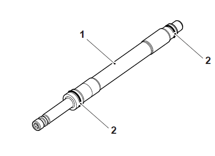
7. Remove and discard the O-rings from the deadshaft.
- Deadshaft
- O-rings
Front Balancer Shaft - Removal
WARNING
Before starting work, ensure the motorcycle is stabilised and adequately supported. This will help prevent it from falling and causing injury to the operator or damage to the motorcycle.
Perform the following operations:
- Seat - Removal
- Battery - Removal
- Fuel Tank - Removal
- Engine - Removal
- Crankcase - Disassembly
Note
- The connecting rods and caps should be identified, using a paint mark or similar
1. Remove and discard the connecting rod bolts.
- Connecting rod bolts
- Connecting rod cap
- Connecting rod
2. Remove the crankshaft.
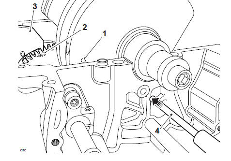
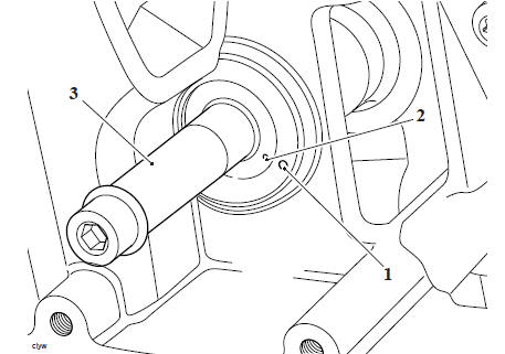
3. Remove the front balancer shaft blanking screw and, discard the washer.
- Blanking screw
- Washer
- Upper crankcase
Note
The front dead shaft clamp is marked with the F facing away from the crankcase.
4. Loosen but do not fully remove the dead shaft clamp locking screw.
5. Remove the dead shaft clamp securing screw and washer. Discard the screw, retain the washer for reuse.
- Dead shaft clamp
- Locking screw
- Securing screw
- Washer
- Dead shaft
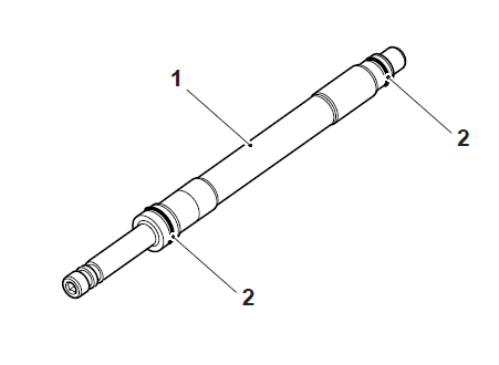
6. Support the balancer shaft and noting its orientation slide the dead shaft from the crankcase.
- Balancer
- Dead shaft
- Dead shaft clamp
7. Remove the balancer shaft.
8. Remove and discard the O-rings from the deadshaft.
- Deadshaft
- O-rings
Balancer shafts - Inspection
1. Inspect all gears for chipped or missing teeth.
2. Inspect all bearings for signs of seizure and any other damage. Check that all bearings rotate smoothly and without tight spots.
Front Balancer Shaft - Installation
WARNING
Before starting work, ensure the motorcycle is stabilised and adequately supported. This will help prevent it from falling and causing injury to the operator or damage to the motorcycle.
Note
To ensure a correct relationship, the balancer shaft must be installed in a specific orientation relative to the crankshaft.
1. Check T3880039 - Idler Gear Timing Pin is fully inserted into the idler gear, and that the camshaft to idler gear timing is correct.
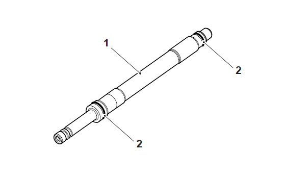
2. Fit a new O-ring to the grooves at each end of the deadshaft.
- Deadshaft
- O-rings
CAUTION
The balancer shaft gear is designed to mesh with the crankshaft gear.
Correct adjustment of the balancer shafts is critical to the performance of the engine and comfort of the rider.
Failure to correctly adjust the balancer shafts may cause serous engine damage and a poor rider experience.
3. Lubricate the balancer shaft, needle roller bearings and O-rings with clean engine oil.
4. Fit the balancer shaft into the crankcase as noted 4. during removal.
5. Support the balancer shaft and noting its orientation, slide the dead shaft through the balancer shaft and into the upper crankcase.
- Balancer
- Dead shaft
- Dead shaft clamp
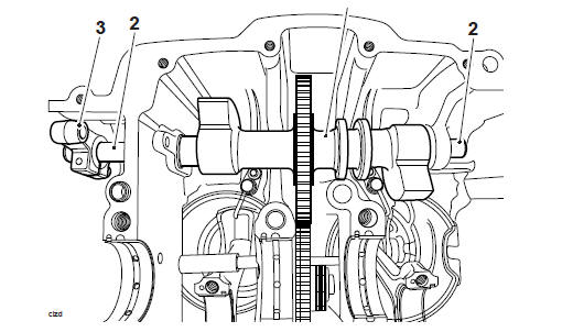
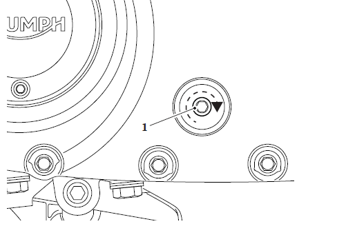
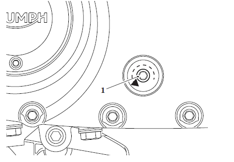
6. Position the alignment mark on the dead shaft with the alignment mark on the crankcase.
Note
- The static alignment of the balancer shaft will allow for initial starting of the engine.
- Final adjustment must be carried out with the engine running and at operating temperature, see Balancer Shafts Dynamic Adjustment.
- Alignment mark (Crankcase)
- Alignment mark (Dead shaft)
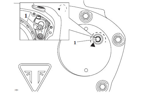
7. Rotate the balancer shaft until the F and dot mark are visible.
8. Position the peg on T3880811 - Front Balancer Timing Tool to the dot mark on the balancer shaft gear.
9. Allow the balancer shaft to rotate anticlockwise until the flat surface rests against the machined surface of the crankcase, as shown.
- Balancer shaft
- Balancer shaft 'F' (front) mark
- Balancer shaft alignment mark
- T3880811 - Front Balancer Timing Tool
- Crankcase
10. Clean the crankshaft, crankshaft bearings and big end bearings with a high flashpoint solvent.
11. Lubricate the crankshaft and bearings with clean engine oil.
12. Position the connecting rods as noted during removal.
Note
As the crankshaft is lowered into position the balancer shaft will rotate and the T3880811 - Front Balancer Timing Tool will no longer rest against the crankcase.
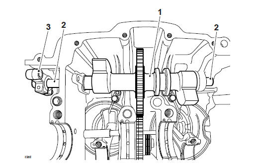
13. Position the crankshaft to the crankshaft bearings, aligning the timing mark on the crankshaft with the machined surface of the crankcase.
- Crankshaft timing mark
- Balancer gear timing marks
- T3880811 - Front Balancer Timing Tool
- T3880601 - Camshaft Timing Pin
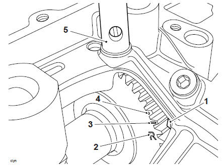
14. To check that the balancer shaft is correctly timed to the crankshaft proceed as follows:
- The alignment hole in the crankshaft is visible through the hole in the crankcase.
- The alignment mark on the balancer shaft is visible through the screw hole in the dead shaft clamp.
- The T3880601 - Camshaft Timing Pin can be inserted fully, locking the crankshaft in position.
- Crankshaft
- Crankshaft dot mark
- Front balancer shaft dot mark
- Dead shaft clamp
Note
If the balancer shafts timing is incorrect, the procedure must be restarted from the beginning.
15. Refit the dead shaft clamp and tighten the new securing screw to 10 Nm and then tighten the dead shaft clamp locking screw to 11 Nm.
- Dead shaft clamp
- Locking screw
- Securing screw
- Washer
- Dead shaft
Perform the following operations:
- Refit the big end caps to the connecting rods Connecting Rod - Installation
- Rear Balancer Shaft - Installation
- Crankcase - Assembly
- Alternator Cover - Installation
- Clutch Cover - Installation
- Camshaft Cover - Installation
- Engine - Installation
- Fuel Tank - Installation
- Battery - Installation
- Seat - Installation
Rear Balancer Shaft - Installation
- Fit a new O-ring to the grooves at each end of the deadshaft
- Deadshaft
- O-rings
2. Lubricate the balancer shaft, needle roller bearings and O-rings with clean engine oil.
3. Position the balancer shaft as noted during removal.
4. Fit the deadshaft into the crankcase as noted during removal and insert the balancer shaft.
CAUTION
The balancer shaft gear is designed to mesh with the crankshaft gear.
Correct adjustment of the balancer shafts is critical to the performance of the engine and comfort of the rider.
Failure to correctly adjust the balancer shafts may cause serous engine damage and a poor rider experience.
Note
- The static alignment of the balancer shaft will allow for initial starting of the engine.
- Final adjustment must be carried out with the engine running and at operating temperature, see Balancer Shafts Dynamic Adjustment.
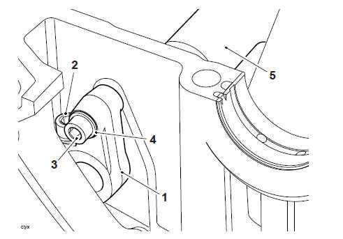
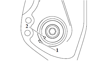
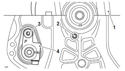
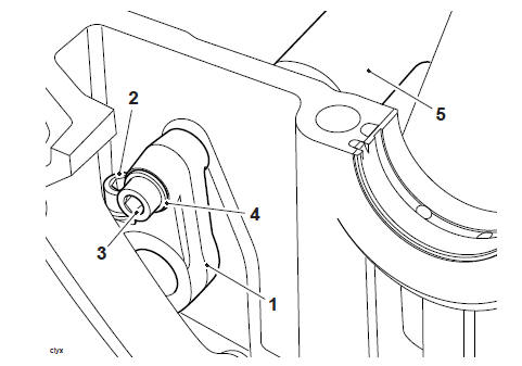
5. Align the dot mark on the dead shaft with the dot mark on the crankcase.
- Crankcase dot mark
- Dead shaft dot mark
- Dead shaft
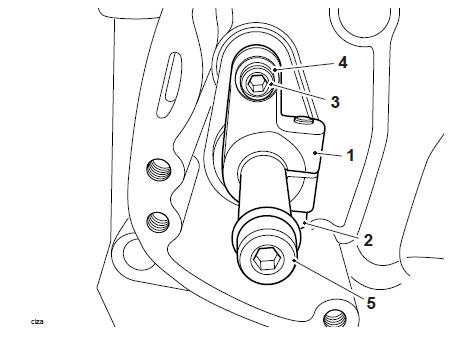
6. Fit a new screw to the washer, install the screw and washer to the dead shaft, ensuring the dot marks are aligned. Tighten to 12 Nm.
7. Position the balancer shaft so that the preload mark aligns with the crankcase identification mark.
8. Refit the dead shaft clamp and tighten the new securing screw to 10 Nm and then tighten the dead shaft clamp locking screw to 11 Nm.
- Dead shaft clamp
- Dead shaft clamp locking screw
- Securing screw
- Washer
- Balancer shaft
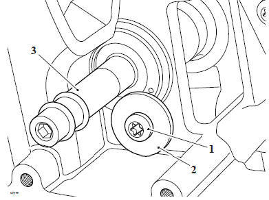
9. Lock the balancer shaft into position using T3880809 - Rear Balancer Timing Tool.
10. Lubricate the crankshaft and bearings with clean engine oil.
- Crankcase identification mark
- Rear alignment mark
- Preload mark
- Dot mark
- T3880809 - Rear Balancer Timing Tool
Perform the following operations:
- Crankcase - Assembly
- Alternator Cover - Installation
- Clutch Cover - Installation
- Camshaft Cover - Installation
- Engine - Installation
- Fuel Tank - Installation
- Battery - Installation
- Seat - Installation
Balancer Shafts Dynamic Adjustment
WARNING
Before starting work, ensure the motorcycle is stabilised and adequately supported. This will help prevent it from falling and causing injury to the operator or damage to the motorcycle.
WARNING
If the engine has recently been running, the engine oil will be hot to the touch.
Contact with the hot oils may cause damage to exposed skin. To avoid skin damage, do not touch hot oil.
WARNING
If the engine has recently been running, the exhaust components may be hot to the touch. Contact with the hot components may cause damage to exposed skin.
To avoid skin damage, always allow the hot parts to cool before working on the exhaust system.
WARNING
The cooling fan is switched on and off by the Engine Control Module in response to a signal received from the coolant temperature sensor. To prevent injury, never place loose clothing, fingers or hands near the cooling fan, until the engine is stopped. Loose clothing, fingers or the hands could become trapped during cooling fan operation and cause crushing injury to the fingers, hands or other parts of the anatomy
WARNING
Never start the engine or run the engine in a confined area. Exhaust fumes are poisonous and can cause loss of consciousness and death within a short period of time. Always operate your motorcycle in the open-air or in an area with adequate ventilation.
Note
- Before dynamically adjusting the front and rear balancer shafts the engine coolant fan must have cycled once and the coolant temperature must be at least 103ºC.
Front Balancer Shaft Dynamic Adjustment
1. Start the motorcycle's engine and allow to run to operating temperature.
CAUTION
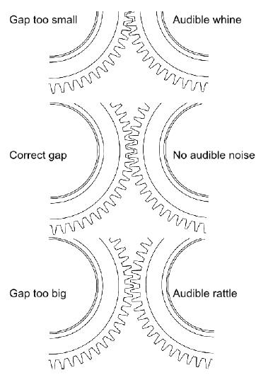
The dead shaft is an eccentric shaft which runs inside the balancer shaft. When rotated the dead shaft therefore closes or opens the gap between the teeth of the balancer gear and the teeth of the crankshaft gear.
If the gap between the balancer gear and crankshaft gear is too small a whine is audible due to the increased load on the gear teeth and bearings.
If the gap between the balancer gear and crankshaft gear is too large a rattle is audible due to the increased gap between the gear teeth.
The balancer shafts must always be adjusted in the same operation.
Adjusting the front or rear balancer shafts individually may cause the engine to whine or rattle.
Unsatisfactory adjustment of the balancer shafts may cause severe engine damage.
2. Stop the engine.
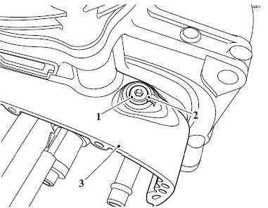
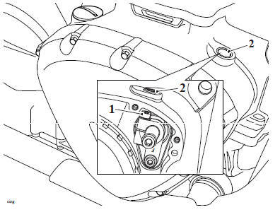
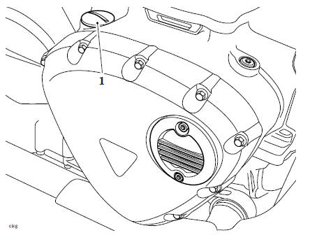
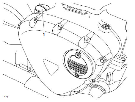
3. Remove the embellisher from the alternator cover and discard the fixings.
4. Remove the dead shaft clamp blanking plug and discard the washer.
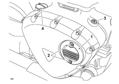
- Embellisher
- Fixings
- Dead shaft clamp blanking plug
- Oil filler cap
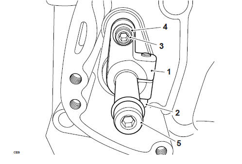
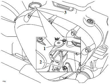
5. Loosen the dead shaft clamp locking screw a maximum of two complete turns to allow smooth rotation of the balancer dead shaft in the clamp.
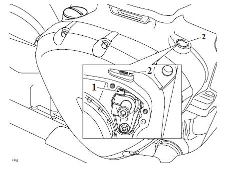
- Dead shaft clamp locking screw
- Blanking plug orifice
CAUTION
When adjusting the balancer shafts do not allow the gears to whine or rattle for a prolonged period.
Allowing the gears to mesh incorrectly for extended periods may cause damage to the gears and or bearings.
6. Start the engine and allow to idle.
7. Gently rotate the dead shaft clockwise until a whining noise can just be heard.
- Dead shaft
8. Rotate the dead shaft anticlockwise until the whining noise can no longer be heard.
- Dead shaft
9. Tighten the dead shaft clamp locking screw to 11 Nm.
10. Stop the engine.
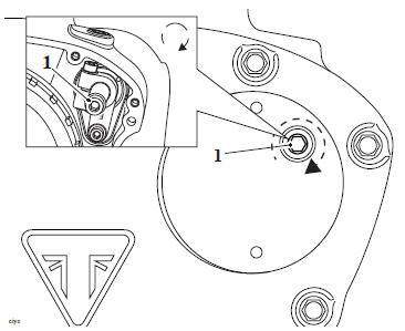
1. Dead shaft clamp locking screw
2. Blanking plug orifice
11. Wipe away any spilled oil from the crankcase.
12. Fit a new washer and tighten the dead shaft clamp blanking plug to 23 Nm.
13. Refit the embellisher cover to the alternator cover, tighten the new fixings to 4 Nm.
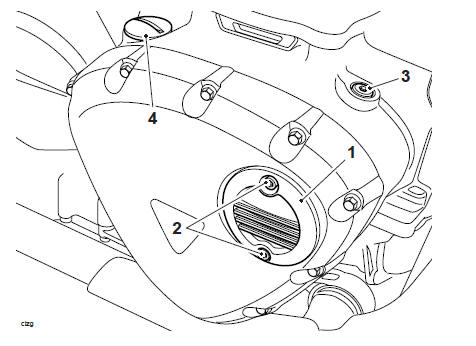
- Embellisher
- Fixings
- Dead shaft clamp blanking plug
- Oil filler cap
Rear Balancer shaft Dynamic Adjustment
- Remove the clutch cover plug.
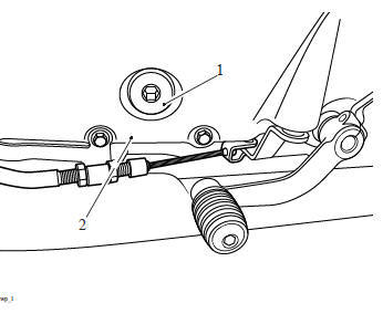
- Clutch cover plug
- Clutch cover
2. Remove the oil filler cap and discard the O-ring.
- Oil filler cap
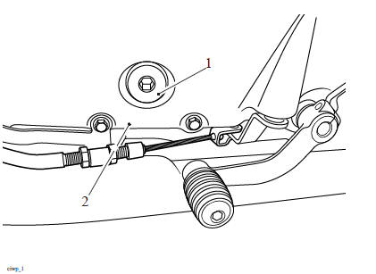
3. Using T3880652 - Dead Shaft Key Tool, loosen the dead shaft clamp locking screw a maximum of two complete turns to allow smooth rotation of the balancer dead shaft in the clamp.
- T3880652 - Dead Shaft Key Tool
- Dead shaft clamp locking screw
- Oil filler orifice
CAUTION
When adjusting the balancer shafts do not allow the gears to whine or rattle for a prolonged period.
Allowing the gears to mesh incorrectly for extended periods may cause damage to the gears and or bearings.
4. Start the engine and allow to idle.
5. Rotate the rear dead shaft clockwise until a whining noise can be heard.
- Dead shaft
6. Rotate the dead shaft anticlockwise until the whining noise can no longer be heard.
- Dead shaft
7. Using T3880652 - Dead Shaft Key Tool tighten the dead shaft clamp locking screw to 11 Nm.
8. Stop the engine.
9. Wipe away any spilled oil from the upper crankcase.
10. Using a new O-ring refit the oil filler cap and tighten to 3 Nm.
- Oil filler cap
11. Refit the clutch cover plug and tighten to 10 Nm.
- Clutch cover plug
- Clutch cover
12. Inspect the engine oil level (see Engine Oil - Level Inspection).
See also:
 Triumph Scrambler 1200 XC - Service manual > Coolant Manifold
Coolant Manifold - Removal WARNING Before starting work, ensure the motorcycle is stabilised and adequately supported. This will help prevent it from falling and causing injury to the operator or damage to the motorcycle.
Triumph Scrambler 1200 XC - Service manual > Transmission
Exploded View - Input and Output Shafts Exploded View - Gear Selector
 Ducati Scrambler
 Fantic Caballero 500
 Indian FTR 1200
 Moto Guzzi V85 TT
 Royal Enfield Bullet Trials Works Replica
 Triumph Scrambler 1200 XE
 Triumph Street Scrambler
 Yamaha XSR700
 Ducati Scrambler 800
 Moto Guzzi V85 TT
 Triumph Scrambler 1200 XC