 Triumph Scrambler 1200 XC - Service manual > Transmission
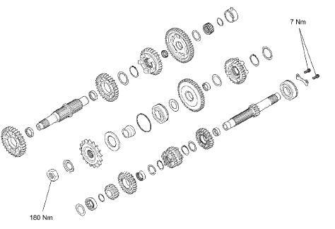
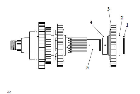
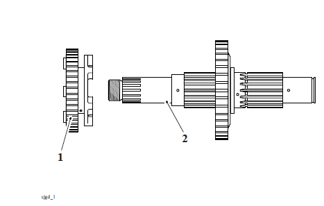
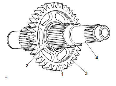
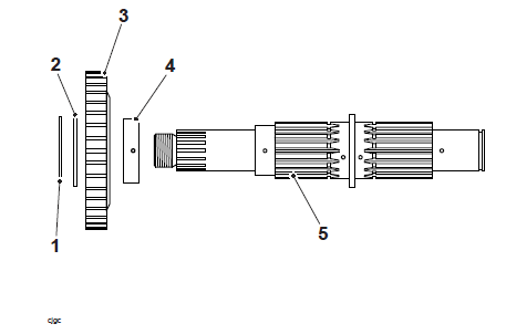
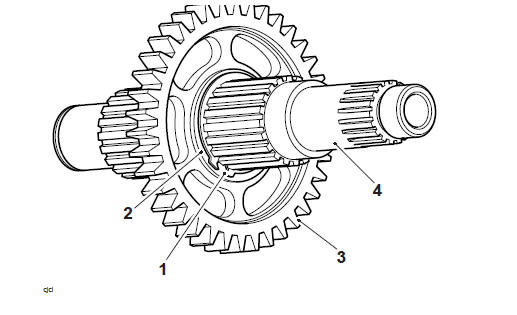
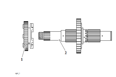
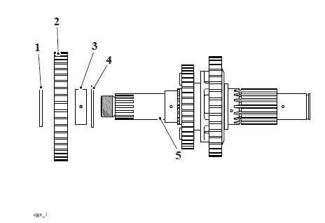
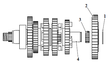
Exploded View - Input and Output Shafts
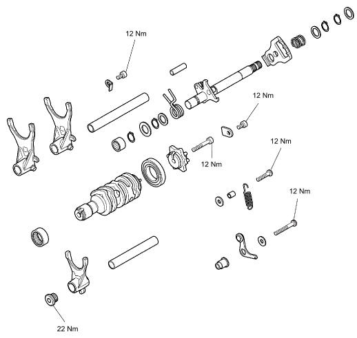
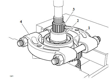
Exploded View - Gear Selector
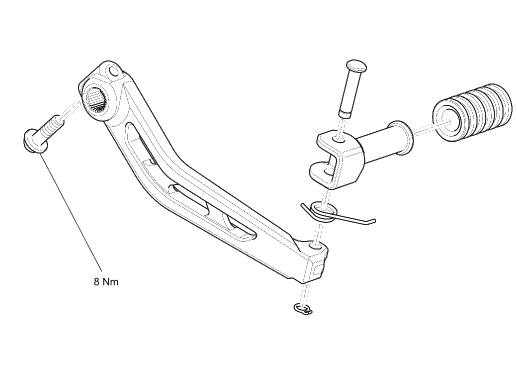
Exploded View - Gear Change Lever
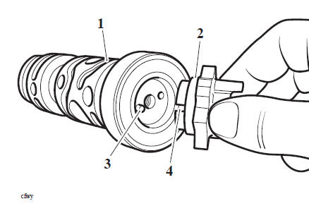
Gear Change Shaft - Removal
WARNING
Before starting work, ensure the motorcycle is stabilised and adequately supported. This will help prevent it from falling and causing injury to the operator or damage to the motorcycle.
Perform the following operations:
- Seat - Removal
- Battery - Removal
- Clutch - Removal
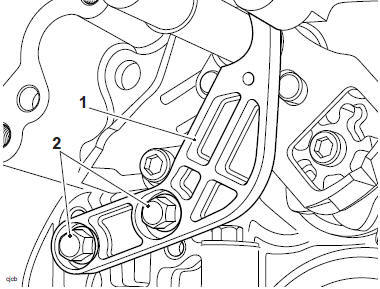
- Remove and discard the fixings and remove the oil pump drive chain guide from the crankcase.
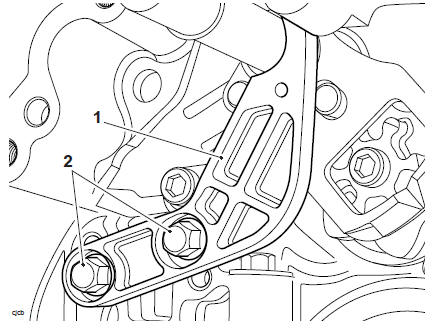
- Oil pump drive chain guide
- Fixings
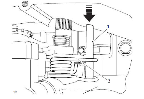
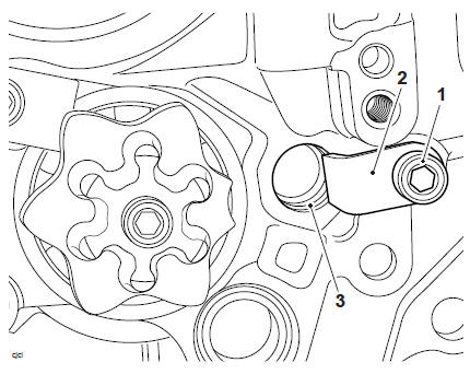
2. Withdraw the abutment dowel from the crankcase.
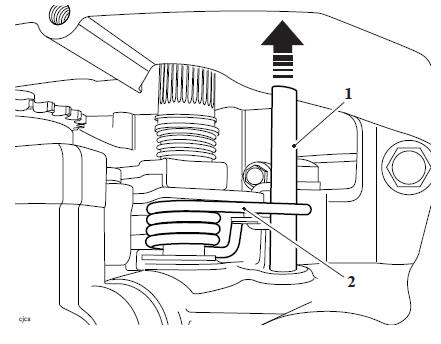
- Abutment dowel
- Abutment spring
3. Collect the washer from the gear change shaft.
4. Withdraw the gear change shaft as an assembly
- Gear change shaft assembly
- Washer
Gear Change Shaft - Inspection
1. Inspect the gear change shaft assembly and spring for damage or wear, the springs for overextension (i.e. abnormal gaps between coils). If any of the components are damaged or worn, replace the complete assembly.
Gear Change Shaft - Installation
WARNING
Before starting work, ensure the motorcycle is stabilised and adequately supported. This will help prevent it from falling and causing injury to the operator or damage to the motorcycle.
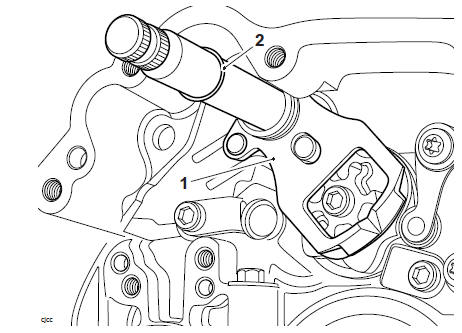
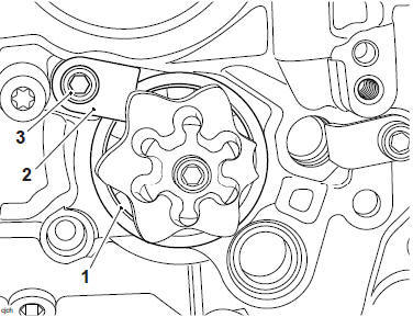
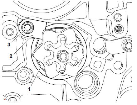
1. Position the selector mechanism into the crankcase and locate the pivot plate to the detent wheel.
- Pivot plate
- Detent wheel
2. Insert the abutment dowel with the spring tangs positioned to either side.
- Abutment dowel
- Abutment spring
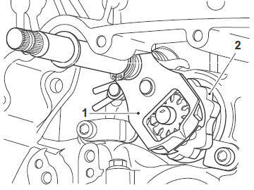
3. Refit the pump drive chain guide to the crankcase. Tighten the new fixings to 7 Nm.
- Pump drive chain guide
- Fixings
Perform the following operations:
- Clutch - Installation
- Battery - Installation
- Seat - Installation
Gear Change Detent Wheel - Removal
WARNING
Before starting work, ensure the motorcycle is stabilised and adequately supported. This will help prevent it from falling and causing injury to the operator or damage to the motorcycle.
Perform the following operations:
- Seat - Removal
- Battery - Removal
- Gear Change Shaft - Removal
- Remove the gear change shaft (see Gear Change Shaft - Removal).
1. Release the detent arm spring.
2. Release the detent arm fixing and remove the detent arm. Discard the fixing.
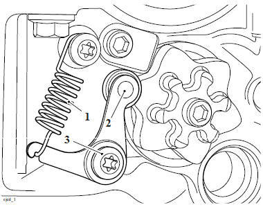
- Detent arm spring
- Detent arm
- Fixing
Note
Note the position of the spacer, detent arm and washer for installation.
3. Remove the fixing and the detent wheel from the selector drum. Discard the fixing.
Gear Change Detent Wheel - Installation
1. Lubricate the selector drum bearings with clean engine oil.
2. Refit the detent wheel to the selector drum, ensuring the pin on the drum locates in the slot in the detent wheel. Prevent the drum from turning and tighten the fixing to 12 Nm.
- Selector drum
- Detent wheel
- Pin
- Slot
3. Refit the spacer, detent arm, washer and a new fixing as noted during removal.
4. Tighten the new fixing to 12 Nm.
5. Refit the detent arm spring.
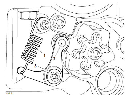
- Detent arm spring
- Detent arm
- Fixing
Perform the following operations:
- Gear Change Shaft - Installation
- Battery - Installation
- Seat - Installation
Selector Forks and Drum - Removal
WARNING
Before starting work, ensure the motorcycle is stabilised and adequately supported. This will help prevent it from falling and causing injury to the operator or damage to the motorcycle.
Perform the following operations:
- Seat - Removal
- Battery - Removal
- Fuel Tank - Removal
- Engine - Removal
- Crankcase - Disassembly
- Remove the transmission shafts
- Gear Change Shaft - Removal
- Gear Position Sensor - Removal
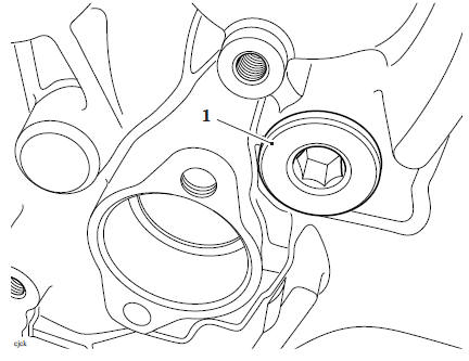
1. Remove and discard the fixing securing the output selector shaft retainer.
- Fixing
- Output selector shaft retainer
- Output selector shaft
2. Remove and discard the fixing securing the input selector shaft.
- Fixing
Note
- Prior to removal, mark, or make a note of the relative positions of each selector fork in the selector drum.
3. Withdraw the input selector shaft and noting its orientation remove the fork.
4. Withdraw the output selector shafts and noting their orientation, collect the two selector forks.
- Output selector shaft
- Input selector shaft
- Selector fork (input shaft)
- Selector fork (output shaft)
- Selector fork (output shaft)
5. Remove the selector drum bearing keeper plate and discard the fixing.
6. Remove the selector drum.
- Selector drum
- Fixing
- Bearing keeper plate
7. If required, remove the fixing and remove the detent wheel from the selector drum.
Discard the fixing.
Selector Forks and Drum Inspection
Inspect all bearings for damage or wear. Renew as necessary.
Inspect the selector forks and selector grooves for wear beyond the service limits.
Renew the components as necessary.
- Refer to the specifications table (see Transmission).
Selector Forks and Drum - Installation
1. If removed, refit the detent wheel to the selector drum, ensuring the pin on the drum locates in the slot in the detent wheel. Prevent the drum from turning and tighten the new fixing to 12 Nm.
- Selector drum
- Detent wheel
- Pin
- Slot
2. Refit the selector drum, ensuring it is pushed fully into the crankcase.
3. Fit the bearing keeper plate and retain the plate in position using a new fixing.
Tighten the fixing to 12 Nm.
- Selector drum
- Bearing keeper plate
- Fixing
4. Lubricate the forks and shafts with clean engine oil.
5. Position the output selector fork shaft and selector forks to the crankcase as noted during removal,
6. Position the input selector fork shaft and selector fork to the crankcase as noted during removal.
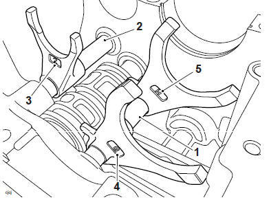
- Output selector shaft
- Input selector shaft
- Selector fork (input shaft)
- Selector fork (output shaft)
- Selector fork (output shaft)
7. Using a new fixing secure the output selector shaft retainer, tighten the fixing to 12 Nm.
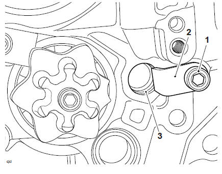
- Fixing
- Retainer
- Selector shaft
8. Using a new fixing secure the input selector shaft, tighten the fixing to 22 Nm.
- Fixing
- Perform the following operations:
- Gear Position Sensor - Installation
- Gear Change Shaft - Installation
- Refit the transmission shafts
- Crankcase - Assembly
- Engine - Installation
- Fuel Tank - Installation
- Battery - Installation
- Seat - Installation
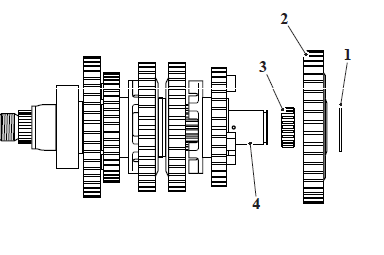
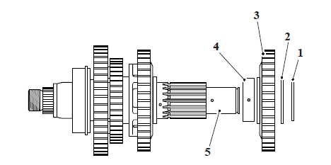
Exploded View - Output Shaft
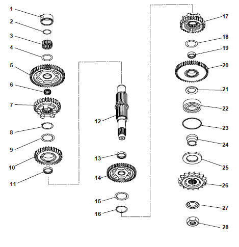
- Bearing outer carrier
- Circlip
- Needle roller bearing
- Thrust washer
- First gear
- Needle roller bearing
- Fifth gear
- Circlip
- Splined thrust washer
- Fourth gear
- Plain bush
- Output shaft
- Plain bush
- Third gear
- Splined thrust washer
- Circlip
- Sixth gear
- Thrust washer
- Plain bush
- Second gear
- Second gear spacer
- Outer bearing
- Snap ring
- Distance sleeve
- Output shaft seal
- Sprocket
- Tab washer
- Sprocket nut
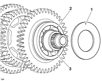
Output Shaft - Disassembly
WARNING
When using a press, always wear overalls, eye, face and hand protection. Objects such as bearings frequently break-up under load and the debris caused during break-up may cause damage and injury to unprotected parts of the body.
Never wear loose clothing, which could become trapped in the press and cause crushing injury to the hand, arms or other parts of the anatomy.
Note
- Make a note or mark the orientation of all transmission parts prior to removal.
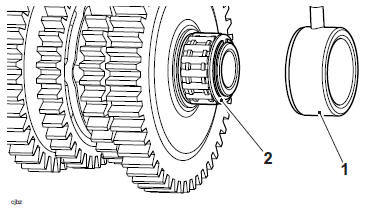
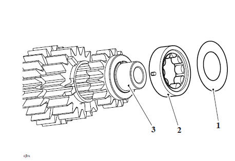
- Mark one side of the needle roller bearing outer carrier to denote its correct orientation and slide it away from the needle roller bearing.
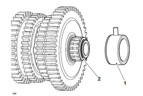
- Bearing outer carrier
- Needle roller bearing
2. Remove and discard the circlip.
3. Noting its orientation, remove the bearing from the output shaft.
4. Remove the thrust washer.
- Circlip
- Needle roller bearing
- Thrust washer
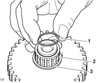
5. Collect the output shaft seal.
- Output shaft seal
- Roller bearing
- Distance sleeve
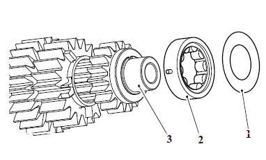
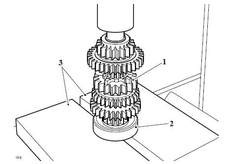
6. Mark one side of first gear to denote its correct orientation and remove it from the shaft.
7. Remove the needle roller bearing from the shaft.
- Thrust washer
- First gear
- Needle roller bearing
- Output shaft
8. Mark one side of fifth gear to denote its correct orientation and remove it from the shaft.
- Fifth gear
- Output shaft
9. Remove the circlip and splined thrust washer.
10. Discard the circlip.
Circlip
2. Splined thrust washer
3. Output shaft
11. Mark one side of fourth gear to denote its correct orientation and remove it from the shaft.
12. Noting its orientation, remove the plain bush which runs inside the gear.
- Circlip
- Splined thrust washer
- Fourth gear
- Plain bush
- Output shaft
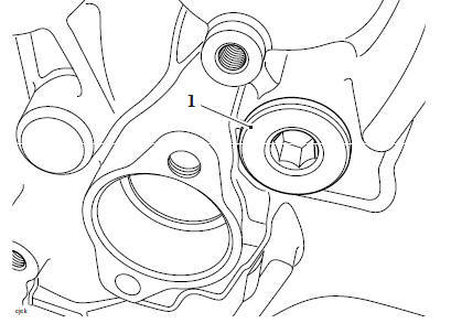
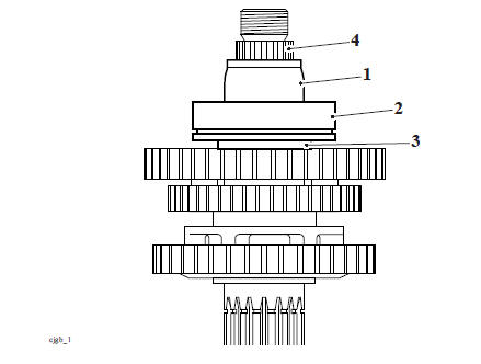
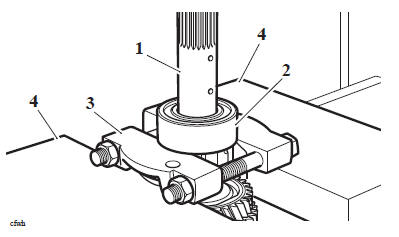
13. Working on the opposite end of the shaft, attach a proprietary bearing separator between the outer bearing and second gear as shown below. Using a press, remove the outer bearing and the distance sleeve.
- Bearing
- Distance sleeve
- Output shaft
- Bearing separator
14. Discard the bearing.
15. Remove the second gear spacer.
16. Mark one side of second gear to denote its correct orientation and remove it from the shaft.
17. Noting its orientation, remove the plain bush from the shaft.
18. Remove the thrust washer from the shaft.
- Second gear spacer
- Second gear
- Bush
- Thrust washer
- Output shaft
19. Noting its orientation, remove the sixth gear.
- Sixth gear
- Output shaft
20. Remove the circlip and the splined thrust washer, discard the circlip.
- Circlip
- Splined thrust washer
- Third gear
- Output shaft
21. Mark one side of third gear to denote its correct orientation and remove it from the shaft.
22. Noting it's orientation, remove the plain bush from the shaft.
- Circlip
- Splined thrust washer
- Third gear
- Third gear bush
- Output shaft
Output Shaft - Inspection
- Examine all gears, bearings, bushes and thrust washers for damage, distortion, chipped teeth and wear beyond the service limits. Replace all defective components and always use new circlips, a new output shaft seal and a new sprocket tab washer to assemble the shaft.
Output Shaft - Assembly
WARNING
When using a press, always wear overalls, eye, face and hand protection. Objects such as bearings frequently break-up under load and the debris caused during break-up may cause damage and injury to unprotected parts of the body.
Never wear loose clothing, which could become trapped in the press and cause crushing injury to the hand, arms or other parts of the anatomy
WARNING
If the oil holes in the output shaft are aligned with the corresponding hole(s), of the bushes or gears engine oil pressure and lubrication will be reduced.
Reduced oil pressure, bush and gear lubrication will cause engine damage and could also lead to engine seizure resulting in loss of motorcycle control and an accident.
CAUTION
Bushes with oil holes must always be MISALIGNED with the corresponding oil holes in the output shaft. Reduced oil pressure and gear lubrication may result from alignment of the oil holes, which would cause premature wear of engine and transmission components.
CAUTION
Removing the output shaft bearing from the shaft will damage the bearing and snap ring. Never reuse removed bearings or snap rings as use of damaged or weakened components could lead to engine and transmission damage.
CAUTION
Press only on the bearing inner race to prevent bearing damage.
Note
Lubricate each gear, thrust washer and bush with clean engine oil during assembly.
1. Locate third gear and the plain bush to the shaft as noted during disassembly.
2. Fit the splined thrust washer and retain with a new circlip as shown below.
- Circlip
- Splined washer
- Third gear
- Output shaft
3. Fit the sixth gear as noted during disassembly.
- Sixth gear
- Output shaft
4. Fit the thrust washer.
CAUTION
Bushes with oil holes must always be MISALIGNED with the corresponding oil holes in the output shaft. Reduced oil pressure and gear lubrication may result from alignment of the oil holes, which would cause premature wear of engine and transmission components.
5. Locate second gear and the plain bush to the shaft as noted during disassembly.
6. Fit the second gear spacer.
- Second gear spacer
- Second gear
- Bush
- Thrust washer
- Output shaft
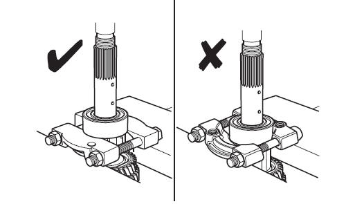
7. Place the output shaft on a press bar, align the inner race of the ball bearing to the output shaft.
8. Press the output shaft through the bearing until the bearing face contacts the thrust washer.
- Output shaft
- Ball Bearing
Note
Ensure the chamfered edge is facing away from the roller bearing.
9. Locate the distance sleeve to the bearing,
10. Press the output shaft through the distance sleeve until it comes into contact with the bearing face.
- Distance sleeve
- Ball bearing
- Spacer
- Output shaft
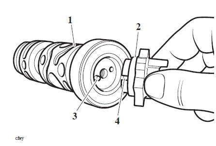
11. Lubricate and fit a new output shaft seal.
- Output shaft seal
- Roller bearing
- Distance sleeve
12. Fit the output sprocket, new tab washer and nut. Do not fully tighten the nut at this stage.
CAUTION
Bushes with oil holes must always be MISALIGNED with the corresponding oil holes in the output shaft. Reduced oil pressure and gear lubrication may result from alignment of the oil holes, which would cause premature wear of engine and transmission components.
13. Working from the opposite end of the shaft, fit the plain bush as noted during disassembly.
14. Fit fourth gear as noted during disassembly
15. Fit the splined thrust washer and retain using a new circlip, as shown below.
- Circlip
- Splined thrust washer
- Fourth gear
- Plain bush
- Output shaft
16. Fit fourth gear as noted during disassembly. Ensure that the smaller dogs face towards fourth gear.
- Fifth gear
- Output shaft
17. Fit the plain bush as noted during disassembly.
18. Fit first gear as noted during disassembly.
19. Fit the thrust washer.
- Thrust washer
- First gear
- Needle roller bearing
- Output shaft
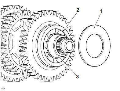
20. Fit the roller bearing to the output shaft as noted during disassembly.
21. Retain the roller bearing using a new circlip.
- Circlip
- Needle roller bearing
- Thrust washer
22. Lubricate the bearing with oil and then slide the bearing outer roller carrier over the needle roller bearing in the orientation noted during disassembly.
- Bearing outer carrier
- Needle roller bearing
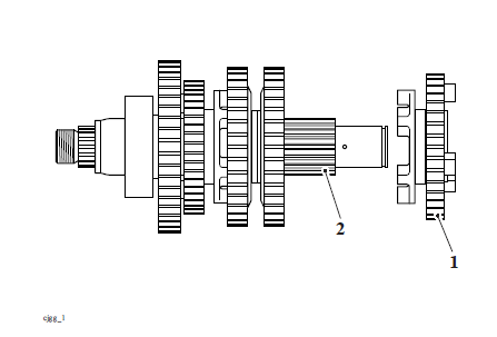
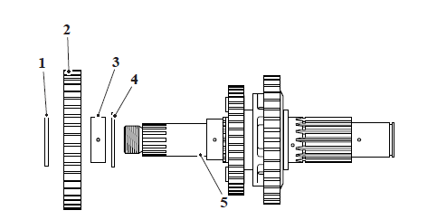
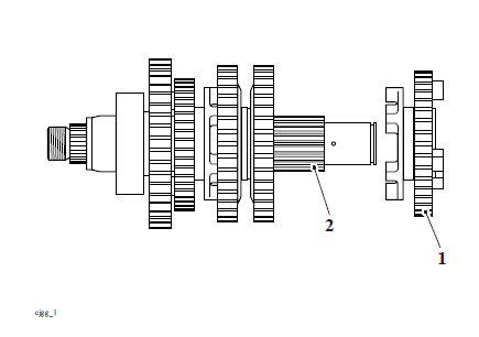
Exploded View - Input Shaft
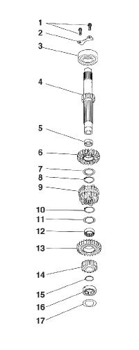
- Bearing retainer bolts
- Bearing retainer plate
- Ball bearing
- Input shaft
- Plain bush
- Fifth gear
- Splined thrust washer
- Circlip
- Third/fourth gear
- Circlip
- Splined thrust washer
- Splined bush
- Sixth gear
- Second gear
- Circlip
- Roller bearing
- Restrictor washer
Input Shaft - Disassembly
WARNING
When using a press, always wear overalls, eye, face and hand protection. Objects such as bearings frequently break-up under load and the debris caused during break-up may cause damage and injury to unprotected parts of the body.
Never wear loose clothing, which could become trapped in the press and cause crushing injury to the hand, arms or other parts of the anatomy.
Note
- The gears on the input shaft can not be fully disassembled or assembled in service. If for any reason a gear requires replacing, the complete input shaft assembly must be replaced.
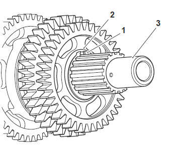
1. Remove the restrictor washer, and roller bearing.
- Restrictor washer
- Roller bearing
- Input shaft
WARNING
When using a press, always wear overalls, eye, face and hand protection. Objects such as bearings frequently break-up under load and the debris caused during break-up may cause damage and injury to unprotected parts of the body.
Never wear loose clothing, which could become trapped in the press and cause crushing injury to the hand, arms or other parts of the anatomy.
- Attach T3880109 - Bearing Separator to the bearing, ensuring the flat side of the tool's jaws are in contact with the bearing.
Service Tool Installation
2. Support the T3880109 - Bearing Separator on press bars, then press the shaft through the bearing. Discard the bearing.
- Input shaft
- Bearing
- T3880109 - Bearing Separator
- Press bars
Input Shaft - Inspection
Examine all gears, bearings, bushes and thrust washers for damage, distortion, chipped teeth and wear beyond the service limits. Replace all defective components.
Input Shaft - Assembly
WARNING
When using a press, always wear overalls, eye, face and hand protection. Objects such as bearings frequently break-up under load and the debris caused during break-up may cause damage and injury to unprotected parts of the body.
Never wear loose clothing, which could become trapped in the press and cause crushing injury to the hand, arms or other parts of the anatomy.
CAUTION
Removing the input shaft bearing from the shaft will damage the bearing. Never reuse removed bearings as use of damaged or weakened components could lead to engine and transmission damage.
Note
Lubricate the bearings with clean engine oil during assembly.
1. Position a new bearing to the input shaft.
2. Support the bearing on press bars as shown below, ensuring that the press bars support the inner race of the bearing.
3. Press the bearing fully on to the shaft.
- Input shaft
- Bearing
- Press plates
4. Fit the roller bearing and restrictor washer to the input shaft.
- Restrictor washer
- Roller bearing
- Input shaft
See also:
 Triumph Scrambler 1200 XC - Service manual > Balancer
Exploded View - Balancers Introduction
Triumph Scrambler 1200 XC - Service manual > Starter Drive and Sprag Clutch
Exploded View - Starter and Sprag Starter Drive/Sprag Clutch - Removal
 Ducati Scrambler
 Fantic Caballero 500
 Indian FTR 1200
 Moto Guzzi V85 TT
 Royal Enfield Bullet Trials Works Replica
 Triumph Scrambler 1200 XE
 Triumph Street Scrambler
 Yamaha XSR700
 Ducati Scrambler 800
 Moto Guzzi V85 TT
 Triumph Scrambler 1200 XC