 Yamaha XSR700 - Owner's Manual > Battery
This model is equipped with a VRLA (Valve Regulated Lead Acid) battery.
There is no need to check the electrolyte or to add distilled water. However, the battery lead connections need to be checked and, if necessary, tightened.
WARNING
Electrolyte is poisonous and dangerous since it contains sulfuric acid, which causes severe burns. Avoid any contact with skin, eyes or clothing and always shield your eyes when working near batteries. In case of contact, administer the following FIRST AID.
- EXTERNAL: Flush with plenty of water.
- INTERNAL: Drink large quantities of water or milk and immediately call a physician.
- EYES: Flush with water for 15 minutes and seek prompt medical attention.
- Batteries produce explosive hydrogen gas. Therefore, keep sparks, flames, cigarettes, etc., away from the battery and provide sufficient ventilation when charging it in an enclosed space.
- KEEP THIS AND ALL BATTERIES OUT OF THE REACH OF CHILDREN.
To access the battery
1. Remove the seat.
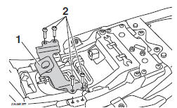
2. Remove the seat holder by removing the bolts.
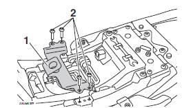
- Seat holder
- Bolt
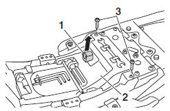
3. Remove the diagnostic connector by pulling it upward.
4. Remove the battery cover by removing the bolts.
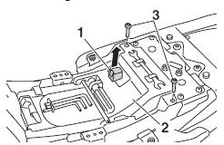
- Diagnostic connector
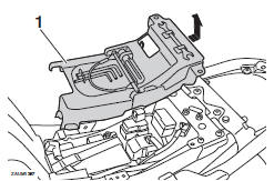
- Battery cover
- Bolt
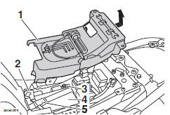
- Battery cover
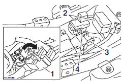
- Positive battery lead (red)
- Negative battery lead (black)
- Battery
- Battery band
To charge the battery
Have a Yamaha dealer charge the battery as soon as possible if it seems to have discharged. Keep in mind that the battery tends to discharge more quickly if the vehicle is equipped with optional electrical accessories.
NOTICE
To charge a VRLA (Valve Regulated Lead Acid) battery, a special (constant- voltage) battery charger is required.
Using a conventional battery charger will damage the battery.
To store the battery
1. If the vehicle will not be used for more than one month, remove the battery, fully charge it, and then place it in a cool, dry place.
NOTICE: When removing the battery, be sure to turn the main switch off, then disconnect the negative lead before disconnecting the positive lead.
2. If the battery will be stored for more than two months, check it at least once a month and fully charge it if necessary.
3. Fully charge the battery before installation.
NOTICE: When installing the battery, be sure to turn the main switch off, then connect the positive lead before connecting the negative lead.
4. When installing the battery, make sure the positive battery lead is routed through the hole in the battery band and that both battery leads are properly connected to the battery terminals.
NOTICE
Always keep the battery charged.
Storing a discharged battery can cause permanent battery damage.
5. Place the battery cover in the original position, and then install the bolts.
6. Install the diagnostic connector by pushing it downward.
7. Install the seat holder by installing the bolts, and then tighten the bolts to the specified torque.
Tightening torque:
Seat holder bolts: 7 N*m (0.7 kgf*m, 5.2 lb*ft)
Replacing the fuses
The main fuse and the fuse boxes are located under the seat.
To access the fuses
1. Remove the seat.
2. Remove the seat holder by removing the bolts.
- Seat holder
- Bolt
3. Remove the diagnostic connector by pulling it upward.
4. Remove the battery cover by removing the bolts.
- Diagnostic connector
- Battery cover
- Bolt
- Battery cover
TIP
To access the main fuse, remove the starter relay cover as shown.
- Starter relay cover
- Fuse box
- Spare main fuse
- Main fuse
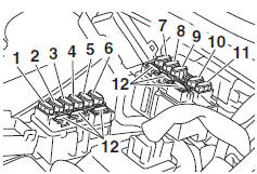
- Ignition fuse
- Signaling system fuse
- Headlight fuse
- Backup fuse 2 (for ECU)
- Backup fuse (for clock and immobilizer system)
- Radiator fan motor fuse
- ABS solenoid fuse
- ABS motor fuse
- Parking lighting fuse
- Auxiliary fuse
- ABS control unit fuse
- Spare fuse
If a fuse is blown, replace it as follows.
1. Turn the main switch off and turn off the electrical circuit in question.
2. Remove the blown fuse, and then install a new fuse of the specified amperage.
WARNING! Do not use a fuse of a higher amperage rating than recommended to avoid causing extensive damage to the electrical system and possibly a fire.
Specified fuses:
Main fuse: 30.0 A
Auxiliary fuse: 2.0 A
Headlight fuse: 15.0 A
Signaling system fuse: 10.0 A
Ignition fuse: 10.0 A
Parking lighting fuse: 7.5 A
Radiator fan motor fuse: 10.0 A
ABS motor fuse: 30.0 A
ABS solenoid fuse: 20.0 A
Fuel injection system fuse: 10.0 A
ABS control unit fuse: 7.5 A
Backup fuse: 7.5 A
Backup fuse 2: 10.0 A
3. Turn the main switch on and turn on the electrical circuit in question to check if the device operates.
4. If the fuse immediately blows again, have a Yamaha dealer check the electrical system.
5. After the fuse is changed, place the battery cover in the original position, and then install the bolts.
6. Install the diagnostic connector by pushing it downward.
7. Install the seat holder by installing the bolts, and then tighten the bolts to the specified torque.
Tightening torque:
Seat holder bolts: 7 N*m (0.7 kgf*m, 5.2 lb*ft)
8. Install the seat.
See also:
 Yamaha XSR700 - Owner's Manual > Drive chain slack
The drive chain slack should be checked before each ride and adjusted if necessary. To check the drive chain slack 1. Place the motorcycle on the sidestand.
Yamaha XSR700 - Owner's Manual > Replacing the headlight bulb
This model is equipped with a halogen bulb headlight. If the headlight bulb burns out, replace it as follows. NOTICE Do not touch the glass part of the headlight bulb. Otherwise the luminosity and the life of the bulb may be adversely affected. Thoroughly clean off any dirt, oil, or fingerprints from the bulb using a cloth moistened with alcohol or thinner. Do not use a headlight bulb of a wattage higher than specified. Do not affix any type of tinted film or stickers to the headlight lens. Do not touch the glass part of the bulb.
 Ducati Scrambler
 Fantic Caballero 500
 Indian FTR 1200
 Moto Guzzi V85 TT
 Royal Enfield Bullet Trials Works Replica
 Triumph Scrambler 1200 XE
 Triumph Street Scrambler
 Yamaha XSR700
 Ducati Scrambler 800
 Moto Guzzi V85 TT
 Triumph Scrambler 1200 XC