 Triumph Scrambler 1200 XC - Service manual > Camshaft Drive
Camshaft Drive Chain Rubbing Blade - Installation
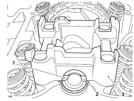
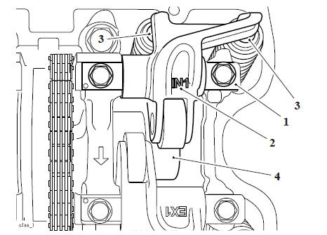
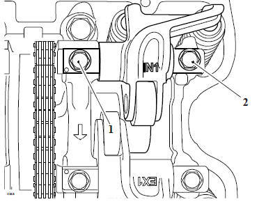
1. Refit the camshaft drive chain rubbing blade. Ensure the lower mounting tip is correctly located in the upper crankcase and the lugs are located in the barrel as noted during removal.
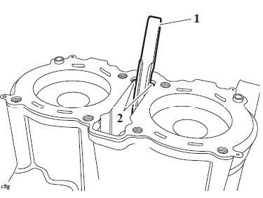
- Camshaft drive chain tensioner rubbing blade
- Mounting lugs
2. Refit the cylinder head (see Cylinder Head - Installation).
3. Refit the camshafts (see Camshaft - Installation).
4. Refit the camshaft cover (see Camshaft Cover - Installation).
Perform the following operations:
- Alternator Cover - Installation
- Engine - Installation
- Fuel Tank - Installation
- Battery - Installation
- Seat - Installation
Camshaft Drive Chain and Idler Gear - Removal
WARNING
Before starting work, ensure the motorcycle is stabilised and adequately supported. This will help prevent it from falling and causing injury to the operator or damage to the motorcycle.
Perform the following operations:
- Seat - Removal
- Battery - Removal
- Fuel Tank - Removal
- Engine - Removal
WARNING
The rotor magnets are very strong. When handling the alternator cover the magnets may 'grab' the stator, causing injury to the hands or fingers. When handling the alternator cover wear suitable gloves and only grip the alternator cover by the outside surfaces; always keep hands and fingers clear when handling the alternator cover
- Alternator Cover - Removal
- Remove the alternator rotor (see Alternator Rotor - Removal).
- Rotate the engine until T3880039 - Idler Gear Timing Pin can be inserted through the hole in the crankcase and into the idler gear.
- Remove the cylinder head (see Cylinder Head - Removal).
- Remove the cylinder barrels (see Barrels - Removal).
WARNING
Never use a 'dot punch' to mark the camshaft drive chain, camshaft or camshaft driven gears. Severe engine damage will result if impact is applied to machined parts.
Note
- To ensure the camshaft drive chain can be refitted in the same orientation, use a suitable marker pen to permanently mark one of the outer plates of the camshaft drive chain prior to removing the camshafts.
- Note the side of which the marked outer plate is facing for installation.
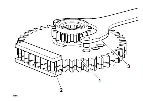
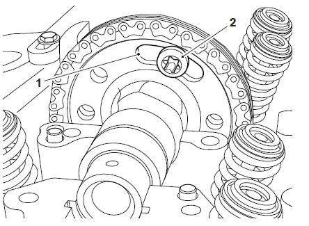
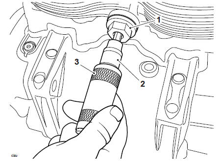
5. Secure the idler gear in position using the locking plate supplied with T3880016 - Balancer Gear C-Spanner-2 by locking the gear teeth as shown below.
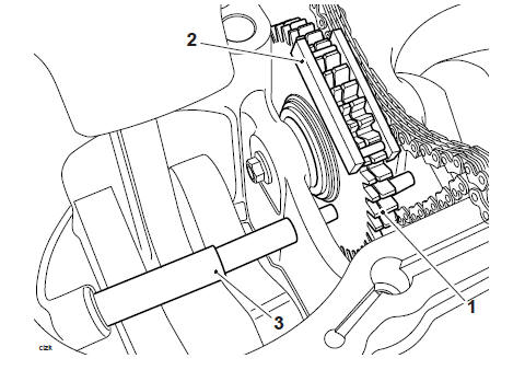
- Idler gear
- Locking plate (Part of T3880016 - Balancer Gear C-Spanner)
- T3880039 - Idler 3. Gear Timing Pin
6. Remove and discard the fixing from the idler gear shaft.
- Fixing
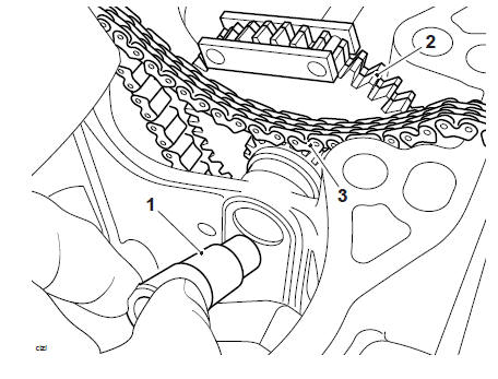
7. Withdraw the idler gear shaft and collect the idler gear and camshaft drive chain from the upper crankcase.
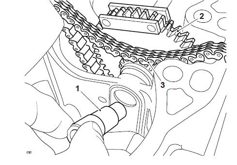
- Idler gear shaft
- Idler gear
- Camshaft drive chain
8. Remove the camshaft drive chain from the idler gear.
Camshaft Chain - Inspection
Visual in situ checks can also be made as follows:
1. Check for significant blue discolouration of the drive chain plates indicating excessive heat build-up.
2. Examine all of the pins for signs of rotation.
3. Check for cracking or deep scratching of the drive chain plates.
4. Check for severe wear of the inner plates as indicated in the diagram below.
For a more thorough check, proceed as follows:
- Remove the drive chain from the engine.
- Suspend the drive chain from a pin or hook with a 13 kg weight attached at the lower end.
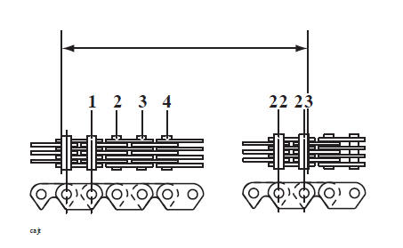
3. Measure across 23 links as shown in the diagram below. If the drive chain is within limits, the measurement should be no longer than 147.50 mm.
Measurements beyond 147.50 mm indicate that the drive chain must be replaced.
4. Check for severe wear of the inner surface of the outer plates at the side-contact points with the sprocket teeth.
5. Check for signs of stiffness or kinking.
6. Check for severe wear of the plates in the area shown below.
7. If any of these symptoms are evident, the camshaft drive chain must be replaced.
Camshaft Drive Chain and Idler Gear - Installation
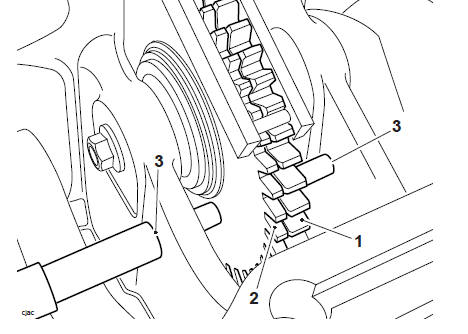
1. Preload the backlash gear using T3880041 - Idler Gear Timing Wrench and locking plate T3880016 - Balancer Gear C-Spanner-2 as shown below.
- Idler gear
- Locking plate (part of T3880016 - Balancer Gear C-Spanner)
- T3880041 - Idler Gear Timing Wrench
2. Install the camshaft drive chain to the idler gear.
3. Refit the idler gear to the upper crankcase and install the idler gear shaft. Ensure that the marked outer plate on the camshaft drive chain is facing the same direction as noted for removal.
- Idler gear shaft
- Idler gear
- Camshaft drive chain
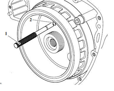
4. Install T3880039 - Idler Gear Timing Pin through the hole in the crankcase (alternator side) and through the smaller hole in the idler gear, as shown below.
- Idler gear
- Backlash gear
- T3880039 - Idler Gear Timing Pin
5. Install the idler gear shaft and a new fixing, Counter hold the idler shaft and tighten the fixing to 10 Nm.
- Fixing
6. Refit the barrel assembly (see Piston - Installation).
7. Refit the cylinder head (see Cylinder Head - Installation).
8. Refit the camshafts (see Camshaft - Installation).
9. Recheck the tensioner plunger location against the camshaft drive chain tensioner blade.
10. Remove T3880601 - Camshaft Timing Pin from the crankcase.
11. Remove T3880039 - Idler Gear Timing Pin from the idler gear.
Perform the following operations:
- Camshaft Cover - Installation
- Alternator Cover - Installation
- Engine - Installation
- Fuel Tank - Installation
- Battery - Installation
- Seat - Installation
Exhaust Decompressors
Note
The decompressor is an integral part of the camshaft. Any internal parts are not serviceable and can only be replaced as part of the camshaft. Always refer to the EPC for parts availability.
Camshaft - Removal
WARNING
Before starting work, ensure the motorcycle is stabilised and adequately supported. This will help prevent it from falling and causing injury to the operator or damage to the motorcycle.
Note
The camshaft can be removed from the cylinder head without complete removal of the camshaft drive chain. However, the camshaft drive chain must first be detached from the camshaft.
Perform the following operations:
- Seat - Removal
- Battery - Removal
- Fuel Tank - Removal
- Ignition Coils - Removal
- Camshaft Cover - Removal
- Alternator Cover - Removal
1. Rotate the engine until T3880601 - Camshaft Timing Pin can be inserted through the hole in the alternator rotor, crankcase and into the idler gear.
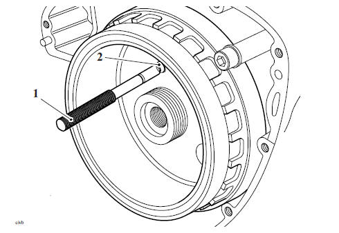
- T3880601 - Camshaft Timing Pin
- Timing hole in alternator rotor
2. In addition to the alignment mark, at TDC, the offset slot on the camshaft will align with the upper surface of the cylinder head.
Note
The T3880650 - Camshaft Timing Plate has two different thickness edges marked A and B. If side A will not slide smoothly into the camshaft slot side use side B.
3. Insert the T3880650 - Camshaft Timing Plate into the camshaft slot. Ensure that the tool is centrally located on the cylinder head and secure as shown below.
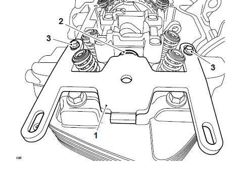
- T3880650 - Camshaft Timing Plate
- Camshaft slot
- Fixings (6 x 12 mm)
4. Remove the camshaft drive chain tensioner (see Camshaft Drive Chain Tensioner - Removal).
CAUTION
To avoid damage to the camshaft frames, always ensure as many camshaft lobes as possible are facing downwards. This will reduce stress on the camshaft frames during removal. Damage to the camshaft frames will result in replacement of the complete cylinder head.
Note
The camshaft frames can be removed either sequentially or simultaneously.
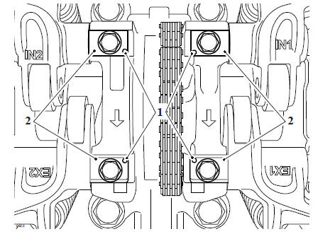
5. Evenly and progressively release the camshaft frame fixings in the sequence shown below.
Camshaft Frame Release Sequence
CAUTION
Failure to release the camshaft frame fixings progressively and evenly may result in damage to the camshaft frame, the camshaft or the cylinder head itself. A damaged camshaft frame cannot be replaced as an individual item. It can only be obtained as part of a new cylinder head.
6. Once all of the upward force on the camshaft frames has been released, collect the bolts.
CAUTION
The camshaft frames are located to the cylinder head with dowels. When removing the camshaft frames collect the dowels at the same time. Failure to collect the dowels could cause them to fall into the crankcase and may cause serious damage to the engine.
7. Remove the camshaft frames.
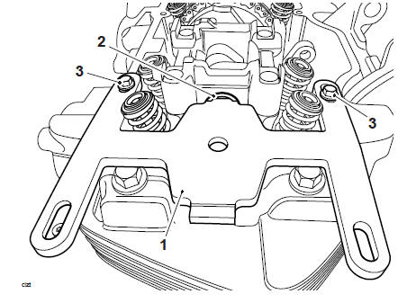
8. Release the front camshaft timing chain tensioner blade and discard the fixings.
9. Raise the camshaft slightly from the bearing journals, and remove the camshaft drive chain tensioner blade.
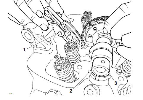
- Tensioner guide
- Bearing journal
- Camshaft
10. Detach the camshaft drive chain from the camshaft.
11. Slide the camshaft to the right and remove it from the cylinder head.
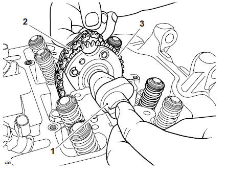
- Camshaft
- Camshaft drive chain
- Camshaft drive gear
12. Secure the camshaft drive chain to prevent it from falling into the crankcase.
Camshaft - Identification
The single camshaft has four lobes; two inlet and two exhaust. The exhaust lobes contain decompressors, operated by the drive gear.
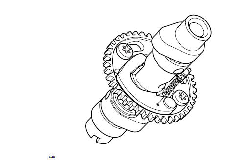
Camshaft
Camshaft - Installation
WARNING
Before starting work, ensure the motorcycle is stabilised and adequately supported. This will help prevent it from falling and causing injury to the operator or damage to the motorcycle.
Accurate camshaft timing can only be obtained using the correct timing method and service tools as described below.
CAUTION
The camshaft sprockets are attached to the camshafts using slotted fixing holes.
This allows for very accurate valve timing and therefore improved performance and fuel economy.
Never fit the camshaft sprockets without correctly setting the camshaft timing using the service tools and timing procedure described below. Severe engine damage will result from incorrect valve timing adjustment.
- If not already installed, install the T3880601 - Camshaft Timing Pin.
- Thoroughly clean the camshaft and journals. Lubricate the camshaft with clean engine oil before fitting to the cylinder head.
Note
- Ensure the sprocket fixings are centrally located within the slotted holes of the sprocket.
- DO NOT tighten the fixings at this stage; the sprocket must be free to rotate.
3. If removed, refit the camshaft sprocket noting its orientation, and secure using the original fixings.
4. Locate the camshaft to the cylinder head from the right hand side, hooking the camshaft drive chain over the sprocket.
5. Align the slot in the camshaft end to the upper surface of the cylinder head.
6. Lift the camshaft slightly from the bearing journals, refit the camshaft drive chain tensioner blade. Tighten the new fixings to 10 Nm.
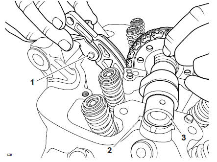
- Tensioner blade
- Bearing journal
- Camshaft
Note
It is not necessary to fit the rocker arms at this stage.
7. Temporarily secure number two cylinder camshaft ladder to the cylinder head with a rocker shaft and one fixing,
- Camshaft slot
- Cylinder head
- Camshaft ladder (cylinder two)
8. Adjust the camshaft sprocket, so that the camshaft chain is taut on the inlet side (rear) of the engine.
9. Ensure there is no slack in the chain between the crankshaft and the sprocket and the sprocket fixings are centrally located within the slotted holes.
- Camshaft slot
- Fixing (one of two on camshaft sprocket)
Note
The T3880650 - Camshaft Timing Plate has two different thickness edges marked A and B. If side A will not slide smoothly into the camshaft slot side use side B.
10. Insert the T3880650 - Camshaft Timing Plate into the camshaft slot. Ensure that the tool is centrally located on the cylinder head and secure as shown below.
- T3880650 - Camshaft Timing Plate
- Camshaft
- Fixings (6 x 12 mm)
11. Check that the camshaft drive chain is engaged around the idler gear and the camshaft sprocket is positioned against the tensioner blade.
12. Fit the T3880651 - Timing Chain Tensioner and tighten to 16 Nm.
- T3880651 - Timing 1. Chain Tensioner
CAUTION
The torque value stated is very important to accurate timing. Always use the correct value of 0.6 Nm, as set using T3880609 - Timing Torque Limiter. Using an incorrect torque value will result in incorrect valve timing being set, or damage to the tensioner blade or other valve train components. Either condition may result in serious damage to the engine, reduced engine performance, or reduced fuel economy.
Note
The T3880609 - Timing Torque Limiter is pre-set to 0.6 Nm.
13. Using the T3880609 - Timing Torque Limiter, tighten the internal screw thread to 0.6 Nm
- T3880651 - Timing Chain Tensioner
- Adaptor
- T3880609 - Timing 3. Torque Limiter
14. Remove and discard the accessible camshaft sprocket fixing. Install a new encapsulated fixing and tighten to 22 Nm.
15. Remove the T3880601 - Camshaft Timing Pin.
CAUTION
Always check that the T3880650 - Camshaft Timing Plate has been removed before rotating the engine. Severe damage will result to the camshafts or T3880650 - Camshaft Timing Plate if engine rotation is attempted with the tool installed.
16. Rotate the engine until the remaining sprocket fixing is accessible.
17. Refit the T3880601 - Camshaft Timing Pin.
18. Remove and discard the remaining camshaft sprocket fixing. Install a new encapsulated fixing and tighten to 22 Nm.
19. Remove T3880601 - Camshaft Timing Pin.
Note
With the aid of an assistant, hold the camshaft drive chain taut during removal of the T3880651 - Timing Chain Tensioner.
20. Release the tension on the T3880651 - Timing Chain Tensioner.
21. Refit the timing chain tensioner, incorporating two new O-rings (see Camshaft Drive Chain Tensioner - Installation).
22. To activate the tensioner, rotate the crankshaft anticlockwise two complete turns, using the fixing fitted to the end of the crankshaft. Stop rotation when number 1 cylinder is at top dead centre (TDC).
Note
Before inserting the timing pin, ensure the slot on the camshaft is aligned with the upper surface of the cylinder head.
23. Insert the T3880601 - Camshaft Timing Pin into the timing holes in the crankcase and crankshaft.
- T3880601 - Camshaft Timing Pin
- Timing hole in alternator rotor
Note
The T3880650 - Camshaft Timing Plate has two different thickness edges marked A and B. If side A will not slide smoothly into the camshaft slot side use side B.
24. Check that the T3880650 - Camshaft Timing Plate fits into the camshaft slot (to check that the camshaft timing has not moved during the removal of the T3880651 - Timing Chain Tensioner.
25. Lubricate the camshaft bearing areas of the camshaft frame with a 50/50 solution of engine oil and molybdenum disulphide grease.
26. Fit the shims to the valves as noted during removal.
27. Position cylinder one camshaft frame to the cylinder head.
- Camshaft ladder (cylinder 2)
- Camshaft ladder (cylinder 1
- Shims (cylinder 2 inlet)
- Shims 4. (cylinder1 inlet)
- Shims (cylinder 2 exhaust)
- Shims (cylinder 1 exhaust)
28. Remove the T3880650 - Camshaft Timing Plate.
29. Remove the T3880601 - Camshaft Timing Pin.
30. Lubricate the threads of the camshaft frame fixings with clean engine oil.
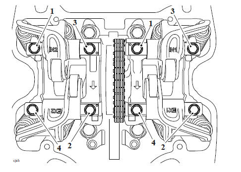
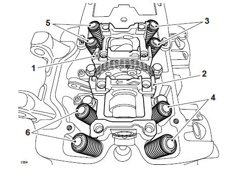
31. Fit the rocker shafts with the dot marks facing upwards and toward the camshaft drive gear.
32. Fit the inlet and exhaust rocker shafts to cylinder number one as shown below.
Do not fully tighten at this stage.
33. Finger-tighten the fixings until the under head areas are in contact with the camshaft frame.
- Fixings (inlet rocker shaft)
- Fixings (exhaust rocker shaft)
- Dot mark
34. Remove the fixing and rocker shaft from cylinder number two camshaft frame.
35. Lubricate the threads of the camshaft frame fixings with clean engine oil.
Note
The rocker shaft must be fitted with the dot marks facing upwards and toward the camshaft drive gear.
36. Fit the inlet and exhaust rockers and shafts to cylinder number two. Do not fully tighten at this stage.
- Dot mark
- Rocker shaft
37. Tighten the fixings hand tight until the rocker shafts are in contact with the camshaft frame.
CAUTION
To avoid damage to the camshaft frame, always ensure as many camshaft lobes as possible are facing away from the rocker shaft. This will reduce stress on the camshaft frame during assembly. Damage to the camshaft frame will result in replacement of the cylinder head.
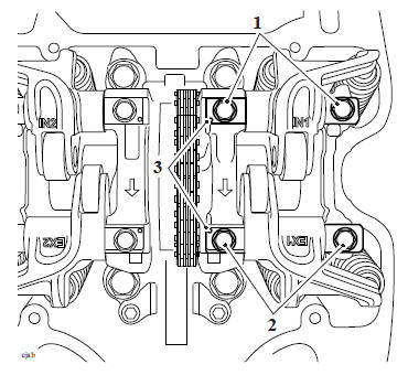
38. In the sequence shown below,
- Tighten cylinder one camshaft frame fixings to 5 Nm.
- Tighten cylinder one camshaft frame fixings to 12 Nm.
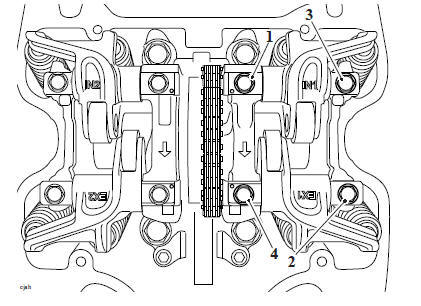
Cylinder One Camshaft Frame Tightening Sequence
- Tighten cylinder two camshaft frame fixings to 5 Nm.
- Tighten cylinder two camshaft frame fixings to 12 Nm.
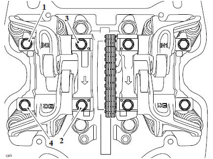
Cylinder Two Camshaft Frame Tightening Sequence
CAUTION
If any components have been renewed, the valve clearances must be checked and adjusted. Running with incorrectly adjusted valve clearances may cause excess engine noise, rough running and engine damage.
39. Check all of the valve clearances and adjust as necessary until the correct clearances are achieved (see Valve Clearance Adjustment).
Perform the following operations:
- Alternator Cover - Installation
- Camshaft Cover - Installation
- Ignition Coils - Installation
- Fuel Tank - Installation
- Battery - Installation
- Seat - Installation
Valve Clearance
Camshaft, valve, valve shim and valve seat wear affect the valve clearances. The effect of this wear is to change the clearance between the rocker and the adjustment shim, causing engine noise and/or improper running. If the valve clearances are incorrect, permanent damage to components in the valve train will take place and engine performance will be affected.
Note
- Valve clearance adjustment must be carried out with the engine cold.
- When replacing a valve shim, always refer to the EPC.
For valve clearance specifications (see Cylinder Head and Valves).
Valve Clearance Adjustment
WARNING
Before starting work, ensure the motorcycle is stabilised and adequately supported. This will help prevent it from falling and causing injury to the operator or damage to the motorcycle.
Perform the following operations:
- Seat - Removal
- Battery - Removal
- Fuel Tank - Removal
Note
- Valve clearance checking and adjustment must be carried out with the engine cold.
1. Remove the camshaft cover (see Camshaft Cover - Removal).
Note
Removing the spark plugs reduces compression therefore allowing the engine to be rotated freely.
2. Remove the spark plugs.
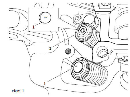
3. Select a high gear and, using the rear wheel, rotate the engine until a camshaft lobe is positioned pointing directly away from the roller on the rocker shaft.
4. Using feeler gauges, measure and record the clearances for this pair of valves only.
- Feeler gauges
5. Measure and record all valve clearances as described previously.
6. Release the two rocker shaft retaining bolts and remove the rocker shaft and rocker arm of a valve that requires adjustment.
- Rocker shaft
- Rocker arm
- Shims (cylinder 1 inlet shown)
- Camshaft
Note
- The underside of the shim displays the shim size.
- Always place the shim with the shim size facing towards the valve.
7. Remove the shim from the valve(s) that requires adjustment.
- Shim
- Valve
8. Measure the original shim, using a micrometer.
9. Calculate the shim thickness required to give the correct clearance, for specifications refer toCylinder Head and Valves.
- Clearance too small - Fit a thinner shim.
- Clearance too large - Fit a thicker shim.
Note
Shims are available ranging from 2.00 mm to 3.20 mm in increments of 0.025 mm.
10. Fit the selected shim to the valve.
11. Refit the rocker arm and shaft, tighten the bolts in the sequence shown below to 10 Nm.
Rocker Shaft Tightening Sequence
12. Repeat the procedure until all valves requiring adjustment have been correctly set.
13. Rotate the engine several times to fully seat the shims.
14. Repeat the clearance checks on all valves, adjust as necessary.
15. Refit the camshaft cover (see Camshaft Cover - Installation).
Perform the following operations:
- Fuel Tank - Installation
- Battery - Installation
- Seat - Installation
See also:
 Triumph Scrambler 1200 XC - Service manual > Cylinder Head
Exploded View - Camshaft and Camshaft Drive
Triumph Scrambler 1200 XC - Service manual > Cylinder Head
Cylinder Head - Removal WARNING Before starting work, ensure the motorcycle is stabilised and adequately supported. This will help prevent it from falling and causing injury to the operator or damage to the motorcycle.
 Ducati Scrambler
 Fantic Caballero 500
 Indian FTR 1200
 Moto Guzzi V85 TT
 Royal Enfield Bullet Trials Works Replica
 Triumph Scrambler 1200 XE
 Triumph Street Scrambler
 Yamaha XSR700
 Ducati Scrambler 800
 Moto Guzzi V85 TT
 Triumph Scrambler 1200 XC