 Triumph Scrambler 1200 XC - Service manual > Cylinder Head
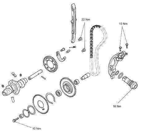
Exploded View - Camshaft and Camshaft Drive
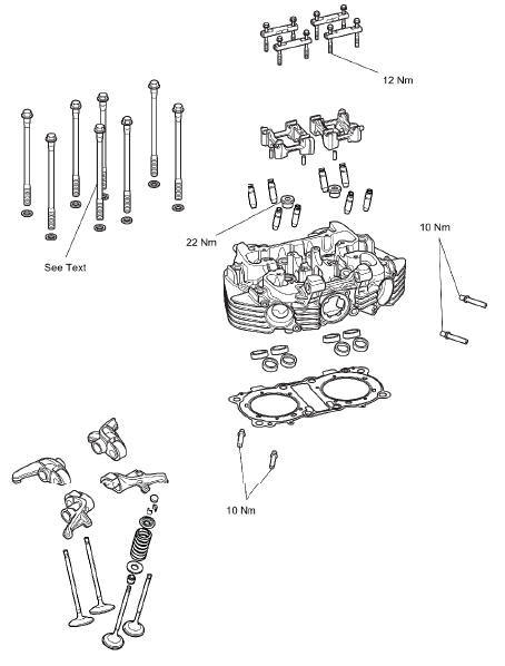
Exploded View - Cylinder Head
Cylinder Head - Description
The engine is fitted with an aluminium alloy cylinder head, which carries the camshaft, valves and spark plugs. The cylinder head is cast as a single entity, to which various components are permanently added after machining.
A silent running camshaft drive chain drives the single overhead camshaft, which runs directly in the cylinder head without additional bearings.
The crankshaft drives an idler gear, which in turn drives the camshaft drive chain. The idler gear, and therefore the camshaft rotates in the opposite direction to the crankshaft.
The engine is fitted with a camshaft drive chain hydraulic tensioner. The tensioner is fed oil via a gallery in the crankcase. The combination of oil pressure and spring pressure pushes the plunger against the tensioner blade which tensions the camshaft drive chain. The hydraulic tensioner has an oil pressure relief valve located in the plunger that is set to open between 12 - 16 bar. The chain is guided by two nylon tensioner blades. The rubbing blade is located in the cylinder barrel by lugs on the blade. The cylinder head must be removed to remove this blade. The tensioner blade is secured to the cylinder head by two bolts at its upper end, and its lower end rests on the tensioner plunger.
Camshaft, valve, valve shim and valve seat wear affect the valve clearances. The effect of this wear is to change the clearance between the rocker and the adjustment shim, causing engine noise and/or improper running. If the valve clearances are incorrect, permanent damage to components in the valve train will take place and engine performance will be affected.
Oil is supplied to the cylinder head by an internal passageway inside the engine.
Once it arrives at the cylinder head, it is passed through a restrictor, and is then delivered to the camshaft bearing journals along grooves and bolt holes in the camshaft frames. The camshaft lobes are splash fed by oil coming from the rocker arms.
Camshaft Drive Chain Tensioner - Removal
WARNING
Before starting work, ensure the motorcycle is stabilised and adequately supported. This will help prevent it from falling and causing injury to the operator or damage to the motorcycle.
Perform the following operations:
- Seat - Removal
- Battery - Removal
- Fuel Tank - Removal
- Ignition Coils - Removal
- Camshaft Cover - Removal
- Alternator Cover - Removal
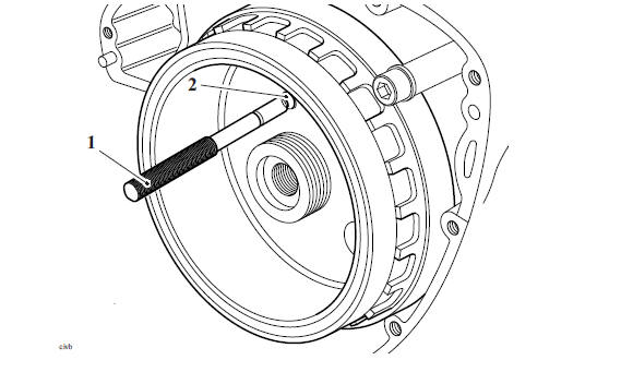
1. Rotate the engine until the T3880601 - Camshaft Timing Pin can be inserted through the hole in the alternator rotor, crankcase and into the idler gear.
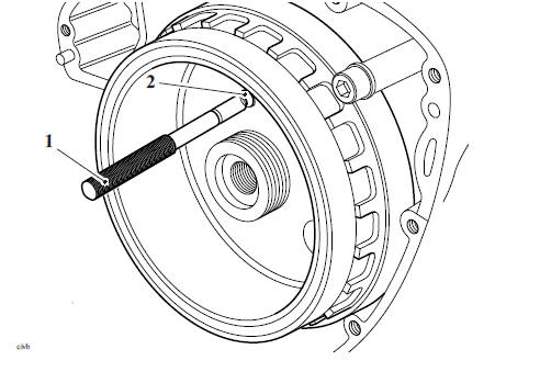
- T3880601 1. - Camshaft Timing Pin
- Timing hole in alternator rotor
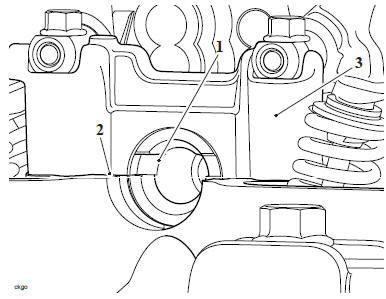
2. In addition to the alignment mark, at TDC, the offset slot on the camshaft will align with the upper surface of the cylinder head.

- Camshaft slot
- Cylinder head
- Camshaft ladder (cylinder two)
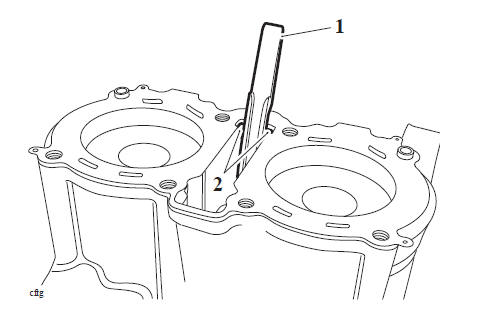
3. With the aid of an assistant, hold the camshaft drive chain tensioner blade to keep the camshaft drive chain in position during removal of the tensioner.
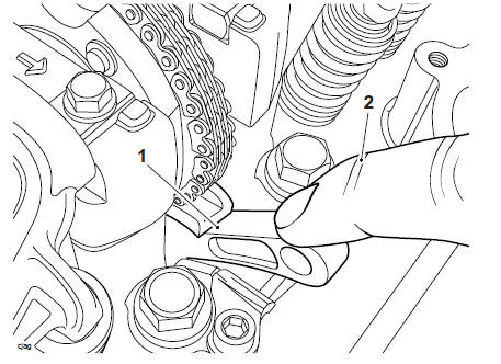
- Camshaft drive chain tensioner blade
- Tension (hand held)
WARNING
The hydraulic tensioner is under spring tension. Always wear hand, eye, and face protection when withdrawing the tensioner. Take great care to minimise the risk of injury and loss of components.
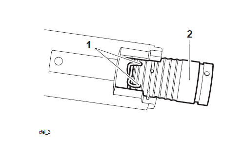
4. Using T3880649 - Timing Chain Tensioner Socket, unscrew the hydraulic tensioner body until the plunger spring tension has been released.
- Tensioner
5. Remove the hydraulic tensioner and discard the O-rings.
Camshaft Drive Chain Tensioner - Inspection
1. Inspect the camshaft drive chain tensioner spring for damage and deformation.
Renew as necessary.
2. Inspect the tip of the camshaft drive chain tensioner plunger for wear and damage. Renew as necessary.
Camshaft Drive Chain Tensioner - Installation
WARNING
Before starting work, ensure the motorcycle is stabilised and adequately supported. This will help prevent it from falling and causing injury to the operator or damage to the motorcycle.
1. Ensure that the camshaft drive chain tensioner blade is in contact with the camshaft drive chain.
2. Check that the camshaft alignment slot aligns with the cylinder head.
3. To set the hydraulic tensioner onto the first tooth of the ratchet (i.e. minimum extension) carry out the following:
Note
- If installing a new hydraulic tensioner, do not release the plunger before fitting.
- If installing the original hydraulic tensioner, the engine oil must be drained out of the tensioner to enable the plunger to be set onto the first tooth of the ratchet.
WARNING
The plunger of the camshaft drive chain tensioner is under spring tension. Always wear hand, eye and facial protection when removing the tensioner as unprotected areas of the body can be injured if the spring tension is released in an unexpected or uncontrolled way.
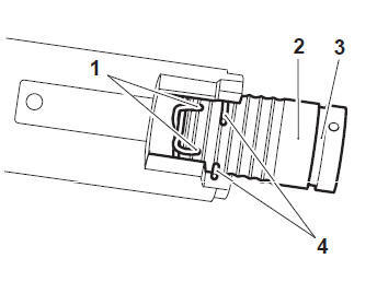
4. Hold the resister ring ends together and pull out the plunger.
- Resister ring ends
- Plunger
5. Remove the spring.
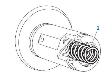
- Spring
6. While holding the resister ring in place, drain the engine oil into a suitable container.
7. Ensure the resister ring is correctly located as shown below.
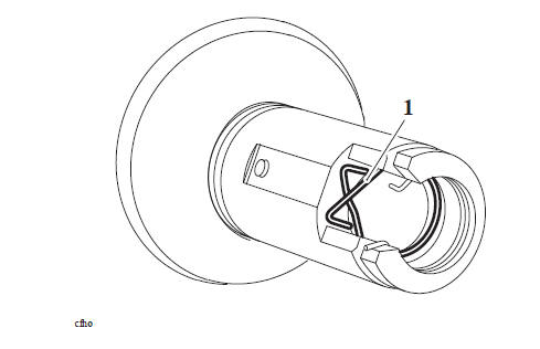
- Resister ring
8. Refit the spring.
9. Support the tensioner in a soft jawed vice.
10. Hold the resister ends together, close the vice allowing the plunger to be pushed through the resister ring until the snap ring aligns with the snap ring groove.
- Resister ring
- Plunger
- Snap ring groove
- Snap ring
11. When the snap ring aligns with the snap ring groove, release the vice and move one end of the snap ring into the groove. Slowly release the plunger to ensure it is held in place.
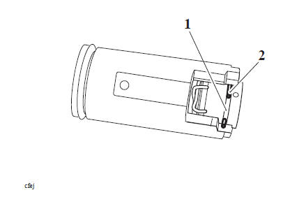
- Snap ring groove
- Snap ring
12. Fit two new O-rings to the camshaft drive chain tensioner body.
13. Fit the tensioner to the cylinder head as noted for removal. Using T3880649 - Timing Chain Tensioner Socket, tighten the tensioner to 16 Nm.
14. Release pressure to the camshaft drive chain tensioner blade, taking care not to move the tensioner blade.
15. Remove T3880601 - Camshaft Timing Pin.
16. To release the plunger from the snap ring holding the hydraulic tensioner, rotate the crankshaft anticlockwise until the plunger is released.
17. Rotate the crankshaft clockwise until the T3880601 - Camshaft Timing Pin aligns with the hole in the crankcase and the crankshaft.
18. Check that there is tension in the camshaft drive chain and the slot at the camshaft end is correctly aligned.
Note
After fitting to the engine, the hydraulic tensioner will be empty of engine oil.
After starting the engine, the camshaft drive chain and tensioner blade will be noisy until full pressure is felt at the tensioner plunger. This could take up to 5 seconds.
19. Check that the tensioner plunger is correctly located in the middle of the camshaft drive chain tensioner blade when viewed from above.
20.Rotate the engine through 4 full revolutions, and reset number 1 cylinder to TDC.
Ensure that the T3880601 - Camshaft Timing Pin aligns with the hole in the crankcase and the crankshaft.
- T3880601 - Camshaft Timing Pin
- Timing hole in alternator rotor
21. Check that the camshaft timing marks align as shown below.
- Camshaft slot
- Cylinder head
- Camshaft ladder (cylinder two)
22. Recheck the tensioner plunger location against the camshaft drive chain tensioner blade.
23. Remove T3880601 - Camshaft Timing Pin.
Perform the following operations:
- Alternator Cover - Installation
- Camshaft Cover - Installation
- Ignition Coils - Installation
- Fuel Tank - Installation
- Battery - Installation
- Seat - Installation
Camshaft Drive Chain Rubbing Blade - Removal
WARNING
Before starting work, ensure the motorcycle is stabilised and adequately supported. This will help prevent it from falling and causing injury to the operator or damage to the motorcycle.
Note
- The camshaft drive chain rubbing blade can only be removed after the cylinder head has been removed.
- The camshaft drive chain tensioner blade can be removed without removing the cylinder head.
Perform the following operations:
- Seat - Removal
- Battery - Removal
- Fuel Tank - Removal
- Engine - Removal
- Alternator Cover - Removal
- Camshaft Cover - Removal
- Rotate the engine until T3880039 - Idler Gear Timing Pin can be inserted through the hole in the alternator rotor, crankcase and into the idler gear.
- Remove the cylinder head (see Cylinder Head - Removal).
Note
Note the position of the camshaft drive chain rubbing blade upper mounting for installation.
3. Lift the camshaft drive chain tensioner rubbing blade out of the crankcase.
- Camshaft drive chain tensioner rubbing blade
- Mounting lugs
See also:
 Triumph Scrambler 1200 XC - Service manual > Camshaft Cover
Camshaft Cover - Removal WARNING Before starting work, ensure the motorcycle is stabilised and adequately supported. This will help prevent it from falling and causing injury to the operator or damage to the motorcycle.
Triumph Scrambler 1200 XC - Service manual > Camshaft Drive
Camshaft Drive Chain Rubbing Blade - Installation 1. Refit the camshaft drive chain rubbing blade. Ensure the lower mounting tip is correctly located in the upper crankcase and the lugs are located in the barrel as noted during removal. Camshaft drive chain tensioner rubbing blade Mounting lugs
 Ducati Scrambler
 Fantic Caballero 500
 Indian FTR 1200
 Moto Guzzi V85 TT
 Royal Enfield Bullet Trials Works Replica
 Triumph Scrambler 1200 XE
 Triumph Street Scrambler
 Yamaha XSR700
 Ducati Scrambler 800
 Moto Guzzi V85 TT
 Triumph Scrambler 1200 XC