 Triumph Scrambler 1200 XC - Service manual > Cylinder Head
Cylinder Head - Removal
WARNING
Before starting work, ensure the motorcycle is stabilised and adequately supported. This will help prevent it from falling and causing injury to the operator or damage to the motorcycle.
Perform the following operations:
- Seat - Removal
- Battery - Removal
- Fuel Tank - Removal
- Engine - Removal
- Camshaft Cover - Removal
- Camshaft - Removal
1. Noting their position and the thickness of the shims, remove all eight shims from the cylinder head.
2. Progressively release the cylinder head bolts in the order shown below.
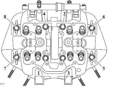
Cylinder Head Bolt Release Sequence
3. Remove the cylinder head bolts, retain the washers and discard the cylinder head bolts.
Note
If necessary, lightly tap the cylinder head with a soft-faced mallet to break the gasket seal.
4. Remove the cylinder head from the crankcase.
5. Remove and discard the cylinder head gasket.
Note
Note the position of the camshaft drive chain rubbing blade upper mounting for installation.
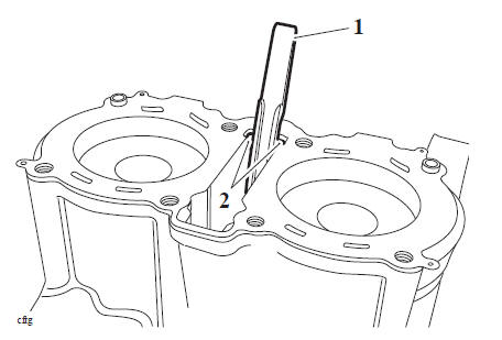
6. Lift the camshaft drive chain tensioner rubbing blade out of the crankcase.
- Camshaft drive chain tensioner rubbing blade
- Mounting lugs
7. Using T3880308 - Cylinder Barrel Clamps and two of the cylinder head bolts, hold the cylinder barrel in position.
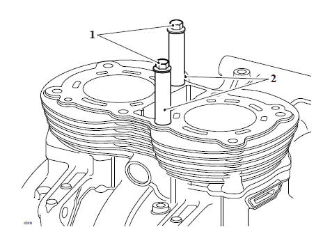
- Cylinder head bolts
- T3880308 - Cylinder Barrel Clamps
Cylinder Head - Inspection
- Thoroughly clean the surface of the cylinder head and check for damage and/or pitting of the combustion chambers.
- Using a straight edge and feeler gauges, check the cylinder head face for warp, which could lead to gasket failure. Replace the cylinder head if warped beyond the flatness limit.
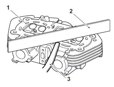
- Cylinder head
- Straight edge
- Feeler gauges
3. For specifications refer to (Cylinder Head and Valves).
4. Inspect the valve guides for damage or wear.
5. If a valve guide is found to be worn beyond the service limit, the complete cylinder head must be renewed.
6. For specifications refer to (Cylinder Head and Valves).
7. Check the camshaft drive chain rubbing blades. Renew if worn or damaged.
CAUTION
Ensure all traces of fluid (coolant, oil etc.) are removed from the threaded holes in the crankcase. Should any fluid remain in any of the threaded holes, severe crankcase damage could result from hydraulic locking of head bolts on assembly of the engine.
Cylinder Head - Installation
1. Thoroughly clean the upper faces of the cylinder barrel.
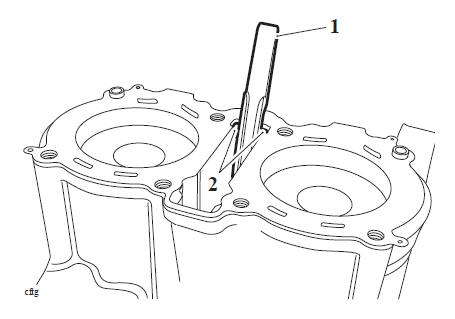
Refit the camshaft drive chain rubbing blade. Ensure the lower mounting tip is correctly located in the upper crankcase and the lugs are located in the barrel as noted during removal.
- Camshaft drive chain tensioner rubbing blade
- Mounting lugs
3. Ensure that both cylinder head dowels are correctly located in the cylinder barrel.
4. Position a new cylinder head gasket to the cylinder barrel, ensuring the gasket is fitted with the lettering uppermost and to the rear of the engine.
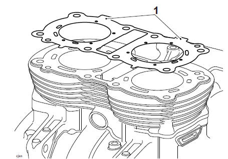
- Head gasket markings
Note
Ensure the drive chain is fitted to the idler gear and located centrally on the tensioner blade.
5. Position the cylinder head over the camshaft drive chain rubbing blade and locate it onto the dowels.
6. Position the washers onto the new cylinder head bolts and lubricate the bolt threads with clean engine oil.
CAUTION
Use the correct procedure to tighten the cylinder head bolts carefully following the four-stage procedure below. This will ensure the long-term reliability of the cylinder head gasket.
Failure to follow the correct tightening procedure may lead to engine damage and premature failure of the cylinder head gasket.
7. In the following sequence, tighten the cylinder new head bolts in four stages as follows:
- Tighten the bolts to 20 Nm.
- Tighten the bolts to 30 Nm.
- Tighten the bolts through a further 150º using T3880105 - Torque Angle Gauge or similar to measure the torque-angle.
- Carry out a torque over-check of the bolts to 60 Nm.
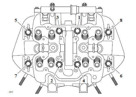
Tightening Sequence
8. Lubricate the valve shims with a 50/50 solution of molybdenum disulphide grease and engine oil, then refit them to their original locations in the cylinder head.
Perform the following operations:
- Camshaft - Installation
- Valve Clearance Adjustment
- Camshaft Cover - Installation
- Engine - Installation
- Fuel Tank - Installation
- Battery - Installation
- Seat - Installation
- Start the engine and allow it to idle while checking for air, oil, coolant and exhaust leaks.
- Rectify as necessary
Valves and Valve Stem Seals
Valves and Valve Stem Seals - Removal
1. Remove each valve from the head using a valve spring compressor. The compressor must act on the valve spring retainer to allow removal of the valve collets.
Valve removal
2, Once the collets are released, remove the following items:
- Valve spring retainer
- Valve spring
- Valve spring base
- Valve stem oil seal
- Valve (deburr before removal).
- Valve stem seal
Note
- Ensure the inlet and exhaust valve components do not become mixed.
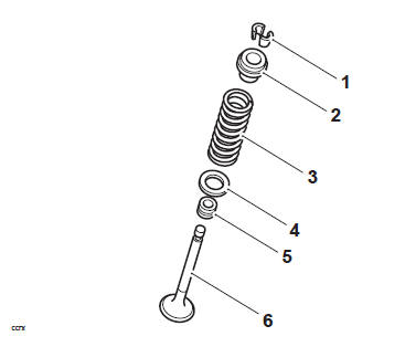
- Collets
- Valve spring retainer
- Valve spring
- Valve spring base
- Valve stem oil seal
- Valve
Valves and Valve Stem Seals - Installation
1, Lubricate the valve stems with a 50/50 solution of engine oil and molybdenum disulphide grease.
2, Install the valve into the valve guide and refit the spring base to the valve spring recess in the head.
3, Fit the valve stem seal over the valve stem and, using a suitable tool, press down fully until the seal is correctly seated over the valve guide.
Note
- During fitment of the valve stem seal, two distinctly different degrees of resistance will be noted when the seal is correctly fitted.
- Firstly, press the seal down the valve stem until the lower side of the seal comes into contact with the valve guide. Greater resistance is felt at this contact point and further gentle pressure is then required to locate the seal over the top end of the valve guide.
- On application of this pressure, the seal can be felt to positively locate over the top face of the valve guide. Once correctly positioned, the seal cannot be pushed down any further.
CAUTION
Incorrect fitment of the valve stem oil seals could lead to high oil consumption and blue smoke emissions from the exhaust system. Do not use excessive force in fitting the seal as this may break the seal ring.
1, Install the valve spring over the valve stem. Ensure the close wound, colour coded ends of the springs are fitted downwards (towards the piston).
2, Fit the valve 2. spring retainer.
3, Compress the valve spring ensuring that the spring is compressed squarely to prevent damage to the valve stem and cylinder head.
4, Fit the valve collets ensuring correct collet location in the spring retainer and valve as the spring compressor is released.
CAUTION
Always check for correct location of the valve collets during and after assembly. If not fitted correctly, the collets may become dislodged when the engine is running allowing the valves to contact the pistons. Any such valve to piston contact will cause severe engine damage.
Valve Face Inspection
Remove any carbon build-up from the valve head area. Examine the valve seat face, checking in particular for signs of cracking or pitting.
Valve Stems
If a valve stem is found to be worn beyond the service limit, the valve must be renewed.
Refer to Cylinder Head and Valves.
See also:
 Triumph Scrambler 1200 XC - Service manual > Camshaft Drive
Camshaft Drive Chain Rubbing Blade - Installation 1. Refit the camshaft drive chain rubbing blade. Ensure the lower mounting tip is correctly located in the upper crankcase and the lugs are located in the barrel as noted during removal. Camshaft drive chain tensioner rubbing blade Mounting lugs
 Ducati Scrambler
 Fantic Caballero 500
 Indian FTR 1200
 Moto Guzzi V85 TT
 Royal Enfield Bullet Trials Works Replica
 Triumph Scrambler 1200 XE
 Triumph Street Scrambler
 Yamaha XSR700
 Ducati Scrambler 800
 Moto Guzzi V85 TT
 Triumph Scrambler 1200 XC