 Ducati Scrambler 800 - Service manual > Diagnostic socket
The diagnostic socket is located in the vehicle rear side. In order to reach it, remove the seat (Removing the seat).
Left-hand switch
In the event of a fault, the internal connections of the device must be checked in all operating conditions. It is therefore necessary to disconnect the main wiring switch connector and perform the check using an analogue or digital multimeter.
Note The same test may be done using the "DDS 2" diagnosis instrument.
LEFT-HAND SWITCH CONTROL
Remove the LH handgrip as described in chapter "Removing the handlebar".
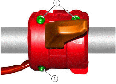
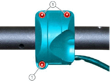
Loosen the screws (1) and remove the left-hand switch.
The colours mentioned in the following descriptions refer to the colour of the wires from the switch and not to the colour of the main electric system wires.
Electric diagram
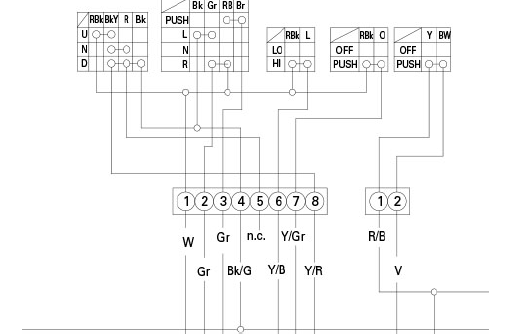
CONTROLS ON LEFT-HAND SWITCH
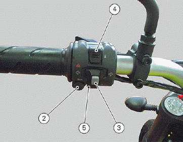
HORN button (2)
Connect the terminals of a multimeter to the Yellow and White/Blue cables to check for electric continuity, which must be available when HORN is pressed.
- When the HORN button is pressed, the resistance value read by the multimeter should be close to zero and, if available, a continuity beep should be heard.
- When the HORN button is not pressed, the resistance value should be
infinity (there is no continuity as the electrical contacts inside the push-button
are open) and no continuity beep should be heard, if provided.
If these conditions are not met, the device must be replaced.
Turn indicator switch (TURN) (3)
The turn indicators cancel button may also be used in the instrument panel for the CONFIRM MENU function, for selecting the riding mode.
Push this button for 3 seconds to the left side to activate the "Hazard" function (all 4 turn indicators).
Connect the multimeter to the Red/Blue and Grey wires arriving from the turn indicator switch and check for electrical continuity when operating the right turn signal.
Repeat the above procedure for the left turn indicator, but connect the multimeter to the Black and Grey wires.
Control switch (SET UP) (SET DOWN) (4) (5)
Buttons used to display and set instrument panel parameters.
Connect the multimeter to the Red and Black wires arriving from the instrument panel function selector switch and check for electrical continuity when pressing button (5).
Repeat the same procedure, press button (4) and connect the multimeter to the Red/Black and Blue/Yellow wires.
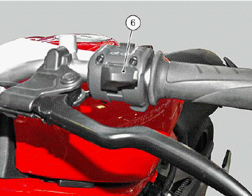
Low beam and high beam (Hi Beam) (6)
Test using the same procedure, applying the probes of the meter to the Red and Blue wires and moving switch down.
Flash switch (PASSING) (6)
The high-beam flash button may also be used for LAP functions.
Check for continuity between the Red and Orange wires.
Unlike the Hi Beam, switch (6) should be pressed.
For the refitting procedure refer to chapter "Refitting the handlebar".
Right-hand switch
In the event of a fault, the internal connections of the device must be checked in all operating conditions. It is therefore necessary to disconnect the main wiring switch connector and perform the check using an analogue or digital multimeter.
Note The same test may be done using the "DDS 2" diagnosis instrument.
RIGHT-HAND SWITCH CONTROL
Remove the RH handgrip as described in chapter "Removing the handlebar".
Loosen screws (1) and remove the right-hand switch by disconnecting it from the main connection. The colours mentioned in the following descriptions refer to the colour of the wires from the switch and not to the colour of the main electric system wires.
Electric diagram
CONTROLS ON RIGHT-HAND SWITCH
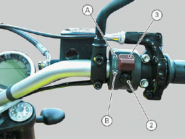
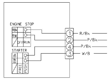
Engine stop button
Using a multimeter, check for continuity between the Red/White and Red/Black wires:
- when button (3) is in RUN position (A), there should be electrical continuity between the two wires;
- when the button is in the OFF position (B), there should be no
electrical continuity between the two wires.
If these conditions are not met, the engine stop switch is not working correctly and must be replaced.
Starter button
Proceed as described for the engine stop button and check for continuity between the Blue/White and Black wires when the starter button (2) is pressed.
If there is no continuity, the starter button is faulty and must be replaced.
Colours mentioned in the descriptions refer to the colour of wires from the switch and not to the colour of the main electric system wires.
For the refitting procedure refer to chapter "Refitting the handlebar".
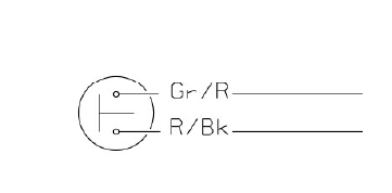
Rear stop switch
The rear STOP switch (1) is located inside the RH footpeg holder plate.
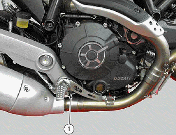
REAR STOP SWITCH CONTROL
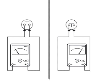
To check operation of the rear (1) STOP switch, use a multimeter: when the rear brake lever is operated, there must be electric continuity between the terminals of the corresponding switch.
No electric continuity should be available when brakes are not operated.
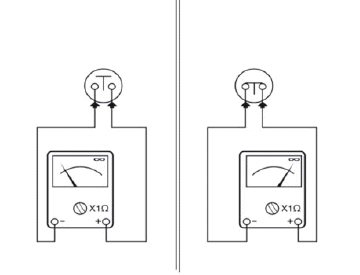
Electric diagram
If these tests fail to produce positive results, the part in question must be replaced.
Gear/neutral sensor
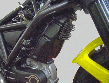
The gear sensor (1) is positioned on the vehicle rear RH side, near the solenoid starter.
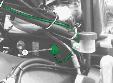
To check the operation of gear sensor (1), connect the DDS 2.
Electric diagram
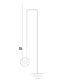
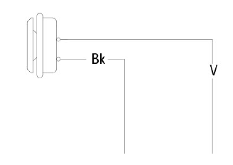
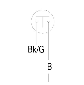
Horn
Supply 12 V (battery) to the two fastons.
With a multimeter connected between the two poles (threaded pins) of the solenoid starter, check for electric continuity.
If there is no electric continuity, ensure that the terminals are not oxidised and apply water repellent spray.
Change the horn if the malfunction persists.
Electric diagram
Clutch switch
The clutch switch (1) is located on the clutch lever lower side.
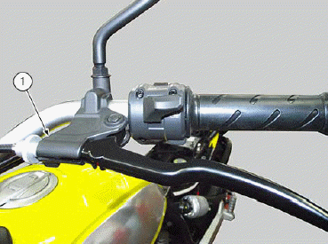
CLUTCH SWITCH CONTROL
To check operation of the front (1) STOP switch, use a multimeter: when the front brake lever is operated, there must be electric continuity between the terminals of the corresponding switch.
No electric continuity should be available when brakes are not operated.
If these tests fail to produce positive results, the part in question must be replaced.
Electric diagram
See also:
 Ducati Scrambler 800 - Service manual > Main relay and injection
To remove and refit the main relay, refer to chapter "Starting system". Timing/rpm sensor The engine rpm sensor (1) is an inductive sensor that detects the teeth of a phonic wheel by means of an alternate signal proportional to the teeth passage speed.
 Ducati Scrambler
 Fantic Caballero 500
 Indian FTR 1200
 Moto Guzzi V85 TT
 Royal Enfield Bullet Trials Works Replica
 Triumph Scrambler 1200 XE
 Triumph Street Scrambler
 Yamaha XSR700
 Ducati Scrambler 800
 Moto Guzzi V85 TT
 Triumph Scrambler 1200 XC