 Moto Guzzi V85 TT - Service manual > General wiring diagram
Electrical system / Electrical system installation / General wiring diagram
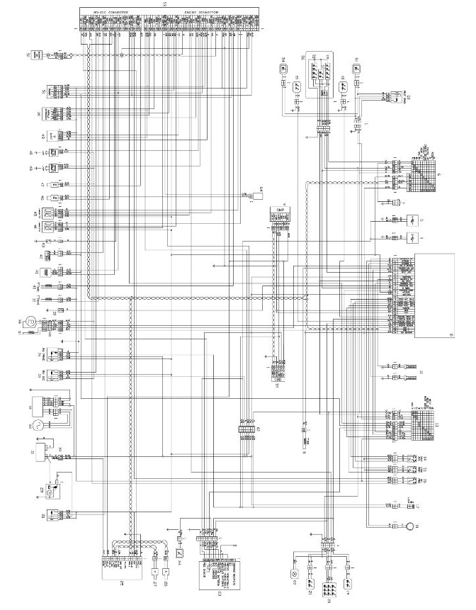
Key:
- Multiple connectors
- -
- -
- -
- USB power sockets (not standard)
- Left light switch
- Horn
- Air temperature sensor
- Predisp. GMP/Tyre pressure
- Instrument panel
- Heated hand grips (not standard)
- Derating Temp. Sens.
- Right light switch
- Frt. brake switch.
- Rear brake switch.
- Clutch switch
- Ignition switch
- Immobilizer antenna
- Right rear turn indicator
- Tail light
- Left rear turn indicator
- Licence plate light
- Antitheft system (not standard)
- Antitheft system LED
- ABS control unit
- Front ABS sensor
- Rear ABS sensor
- Starter motor relay
- Starter motor
- Voltage regulator
- Battery
- Alternator
- Low fuel probe
- OBD connector
- Secondary injection relay
- Primary injection relay
- Fuel level sensor
- Fuel pump
- Oil pressure sensor
- Head temperature Sens.
- Fall Sens.
- Stand switch
- Neutral sensor
- Right cylinder lambda
- Left cylinder lambda
- Right cylinder injector
- Left cylinder injector
- Coils
- T-Map sensor
- Motorised throttle valve
- Demand sensor
- Engine speed sensor
- Engine control unit
- Left fog light (not standard)
- Left Frt. turn indicator
- Front headlamp
- Position lights and DRL
- High beam LED module
- Low beam LED module
- Right Frt. turn indicator
- Right fog light (not standard)
- Secondary fuses
- Fog light relay (not standard)
- Secondary air system
- Ferrite
- -
Colour key:
- Ar Orange
- Az Light blue
- B Blue
- Bi White
- G Yellow
- Gr Grey
- M Brown
- N Black
- R Red
- V Green
- Vi Violet
- Ro Pink
See also:
 Moto Guzzi V85 TT - Service manual > Back side
TABLE A - WIRING ON THE SEAT PILLAR Medium sized cable ties Once the lower seat pillar closing is mounted, remove the two clamps (1)
Moto Guzzi V85 TT - Service manual > Storing new keys
NOTE REGARDLESS OF THE LANGUAGE SET IN THE DASHBOARD FUNCTIONS, THE KEY PROGRAMMING PROCEDURE CAN ONLY BE VIEWED IN ENGLISH. To carry out the one or more key programming procedures, up to a maximum of four, you must connect the motorcycle to the diagnostic tool. Turn key to "ON" and insert the USER CODE where required. Carry out the self-diagnosis of the dashboard and enter the "SETTINGS" section by clicking on "RESET KEYS". At this point, a screen with a warning message will be visible. Press "OK" and start programming the keys.
 Ducati Scrambler
 Fantic Caballero 500
 Indian FTR 1200
 Moto Guzzi V85 TT
 Royal Enfield Bullet Trials Works Replica
 Triumph Scrambler 1200 XE
 Triumph Street Scrambler
 Yamaha XSR700
 Ducati Scrambler 800
 Moto Guzzi V85 TT
 Triumph Scrambler 1200 XC