 Triumph Scrambler 1200 XC - Service manual > Headstock Bearings
Headstock Bearings - Lubricate
WARNING
Before starting work, ensure the motorcycle is stabilised and adequately supported. This will help prevent it from falling and causing injury to the operator or damage to the motorcycle.
Perform the following operations:
- Lower Yoke and Headstock Bearings - Removal
1. Inspect the headstock bearings for damage/wear, (see Headstock Bearing - Inspection).
2. Lubricate the headstock bearings, using finger pressure, force five grammes of Castrol LCX 222 or an equivalent heavy duty lithium based grease between the inner race and the carrier.
3. Rotate the ball bearing to ensure that the grease is distributed over the entire circumference of the internal parts.
4. Any excess grease should be smeared on the outside of the rollers.
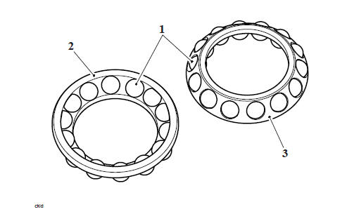
- Roller bearing
- Inner carrier face
- Outer carrier face
Headstock Bearing - Inspection
WARNING
Only remove raised witness marks from within the frame. Removal of material below any raised areas will reduce the level of interference between the frame and the bearings. Loss of interference could cause the bearing to become loose in the frame leading to loss of motorcycle control and an accident.
1. Examine the frame for any raised witness marks caused by the removal process.
Remove any such marks with fine emery paper or a suitable file.
Brake Pad Wear Inspection
WARNING
Before starting work, ensure the motorcycle is stabilised and adequately supported. This will help prevent it from falling and causing injury to the operator or damage to the motorcycle.
In accordance with the Scheduled Maintenance chart, inspect the brake pads for wear. The minimum thickness of lining material for any front or rear brake pad is 1.5 mm. If any pad has worn to the bottom of the groove in the pad centre, replace all the brake pads on that wheel.
- Brake pads
- Minimum thickness line
WARNING
Do not replace individual brake pads; replace both pads in the brake caliper. On the front where two calipers are mounted on the same wheel, all the pads in both calipers must be replaced simultaneously. Replacing individual pads will reduce braking efficiency and may cause loss of motorcycle control and an accident.
Brake Fluid Level Inspection
WARNING
Before starting work, ensure the motorcycle is stabilised and adequately supported. This will help prevent it from falling and causing injury to the operator or damage to the motorcycle.
In accordance with the Scheduled Maintenance chart, inspect the brake fluid level in the front and rear master cylinder reservoirs.
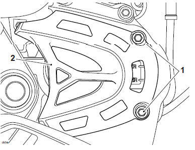
Front Brake Fluid Reservoir
1. The brake fluid level must be kept between the upper and lower level lines with the motorcycle on its side stand and the steering on full left lock.
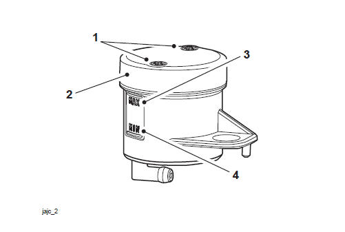
- Fixings
- Reservoir cap
- Upper level line
- Lower level line
Front Brake Fluid Level Adjustment
1. Remove the two fixings.
2. Remove the reservoir cap and the diaphragm seal.
3. Fill the reservoir to the upper level line using new DOT 4 fluid from a sealed container.
4. Refit the reservoir cap and diaphragm seal ensuring that the diaphragm seal is correctly positioned between the cap and the reservoir body.
5. Refit the two fixings and tighten to 0.7 Nm.
Rear Brake Fluid Reservoir
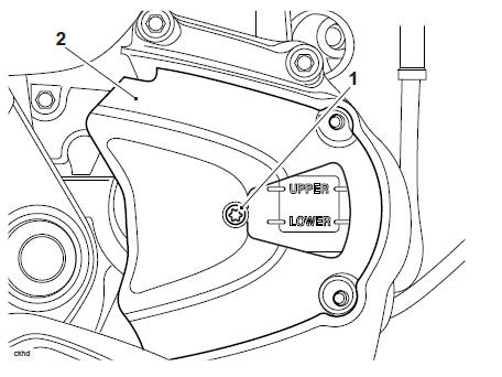
1. The reservoir fluid level lines are visible on the right hand side of the motorcycle on the front sprocket cover
2. The brake fluid level must be kept between the upper and lower level lines (reservoir held horizontal).
- Upper level line
- Lower level line
Rear Brake Fluid Level Adjustment
1. Release the fixings and remove the front sprocket outer cover.
- Fixings
- Sprocket outer cover
Note
The fixing securing the front sprocket middle cover also secures the brake fluid reservoir to the sprocket cover.
2. Release the fixing and remove the front sprocket middle cover. Discard the fixing.
- Fixings
- Sprocket middle cover
3. Detach the brake fluid reservoir from the sprocket cover.

- Brake fluid reservoir
- Sprocket cover
4. Release the cap screws and remove the reservoir cover noting the position of the sealing diaphragm.
5. Fill the reservoir to the upper level line using new DOT 4 fluid from a sealed container.
6. Refit the reservoir cap ensuring that the diaphragm seal is correctly positioned between the cap and the reservoir body. Tighten the cap retaining screws to 1 Nm.
7. Attach the brake fluid reservoir to the sprocket cover.
8. Refit the sprocket middle cover and tighten the new fixing to 3 Nm.
9. Refit the sprocket outer cover and tighten the fixings to 9 Nm.
Brake Calipers - Inspection
WARNING
Before starting work, ensure the motorcycle is stabilised and adequately supported. This will help prevent it from falling and causing injury to the operator or damage to the motorcycle.
WARNING
Always renew caliper seals and pistons after removal from the caliper. An effective hydraulic seal can only be made if new components are used.
A dangerous riding condition leading to loss of control of the motorcycle or an accident could result if this warning is ignored.
- Check for correct brake operation and that the caliper pistons are not
seized.
Rectify as necessary.
- Inspect the brake calipers for fluid leaks. Rectify as necessary
Brake Master Cylinders - Inspection
WARNING
Before starting work, ensure the motorcycle is stabilised and adequately supported. This will help prevent it from falling and causing injury to the operator or damage to the motorcycle.
Inspect both the front and rear master cylinders for fluid leaks. Rectify as necessary.
Final Drive Chain Adjustment
WARNING
Before starting work, ensure the motorcycle is stabilised and adequately supported. This will help prevent it from falling and causing injury to the operator or damage to the motorcycle.
Drive Chain Free Movement Inspection
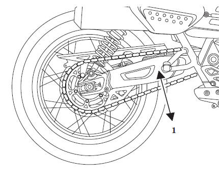
- Maximum movement position
1. Place the motorcycle on a level surface and hold it in an upright position with no weight on it.
2. Rotate the rear wheel by pushing the motorcycle to find the position where the drive chain has least slack. Measure the drive chain's vertical movement, midway between sprockets.
3. If correct, the vertical movement of the drive chain mid-way between the sprockets should be 20 - 30 mm.
Drive Chain Free Movement Adjustment
1. Loosen the wheel spindle nut.
2. Release the lock nuts on both the left hand and right hand chain adjuster bolts.
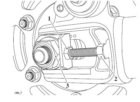
- Adjuster bolt
- Adjuster bolt lock nut
- Rear wheel spindle nut
3. Moving both adjusters by an equal amount, turn the adjuster bolts clockwise to increase chain free-movement and anticlockwise to reduce chain free-movement.
4. When the correct amount of chain free-movement has been set, push the wheel into firm contact with the adjusters.
CAUTION
Check for equal adjustment on both sides using the graduation marks on the swinging arm.
5. Tighten both adjuster lock nuts to 20 Nm and the rear wheel spindle nut to 110 Nm.
6. Repeat the chain adjustment check. Readjust if necessary.
WARNING
Operation of the motorcycle with insecure adjuster lock nuts or a loose wheel spindle may result in impaired stability and handling of the motorcycle. This impaired stability and handling may lead to loss of motorcycle control and an accident.
See also:
 Triumph Scrambler 1200 XC - Service manual > Tyres - Check For Wear/Damage
WARNING Before starting work, ensure the motorcycle is stabilised and adequately supported. This will help prevent it from falling and causing injury to the operator or damage to the motorcycle.
Triumph Scrambler 1200 XC - Service manual > Drive Chain and Sprocket Wear Inspection
WARNING Before starting work, ensure the motorcycle is stabilised and adequately supported. This will help prevent it from falling and causing injury to the operator or damage to the motorcycle. Measurement across 20 links 10 - 20 kg Weight
 Ducati Scrambler
 Fantic Caballero 500
 Indian FTR 1200
 Moto Guzzi V85 TT
 Royal Enfield Bullet Trials Works Replica
 Triumph Scrambler 1200 XE
 Triumph Street Scrambler
 Yamaha XSR700
 Ducati Scrambler 800
 Moto Guzzi V85 TT
 Triumph Scrambler 1200 XC