 Triumph Scrambler 1200 XC - Service manual > Removal and Installation - Fuel and Air Components
Fuel Cap Cover - Removal
Fuel Cap Cover - Installation
Fuel Tank - Removal
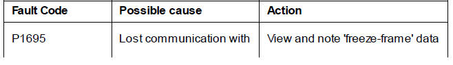
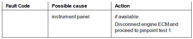
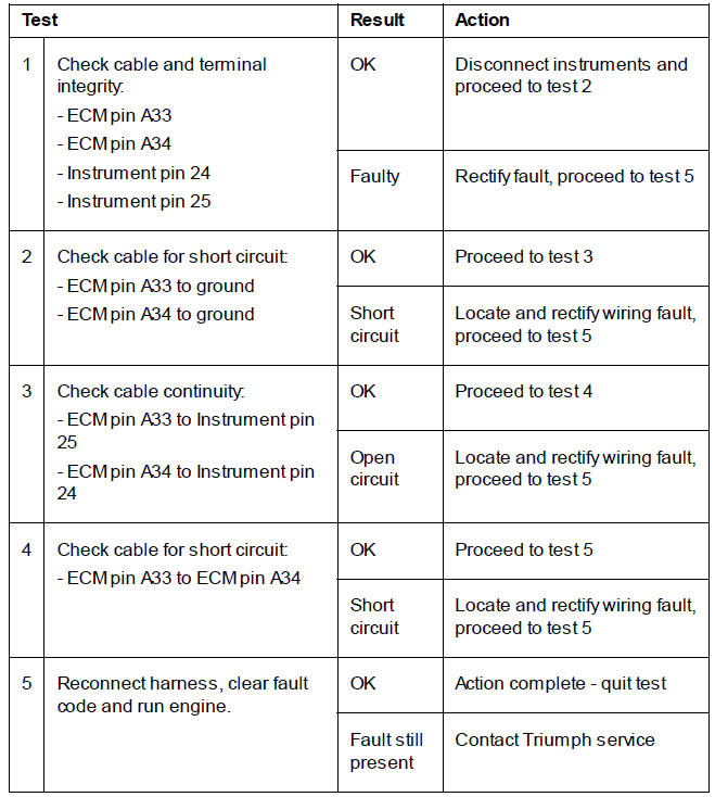
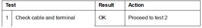
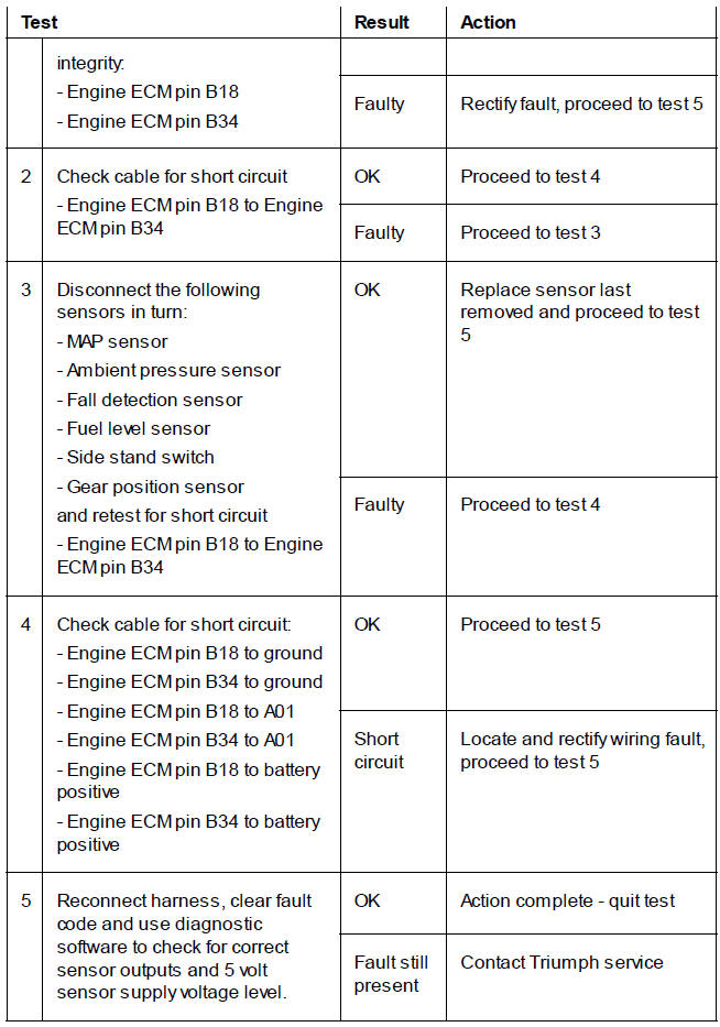
Pinpoint Tests
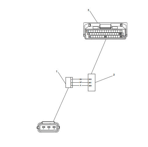
Circuit Diagram
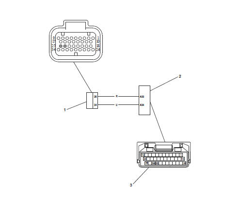
- Instruments
- Engine Electronic Control Module
- Engine Electronic Control Module - Connector A
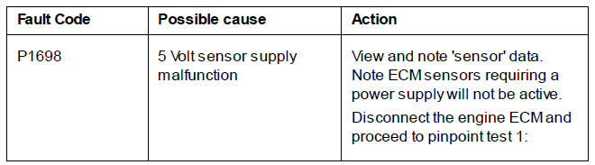
Pinpoint Tests
Circuit Diagram
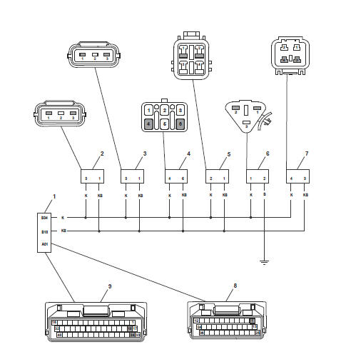
- Engine Electronic Control Module
- Ambient Air Pressure Sensor
- MAP Sensor
- Fall Detection Switch
- Fuel Level Sender
- Side Stand Switch
- Gear Position Sensor
- Engine Electronic Control Module - Connector A
- Engine Electronic Control Module - Connector B
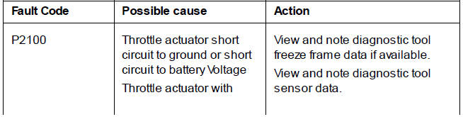
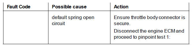
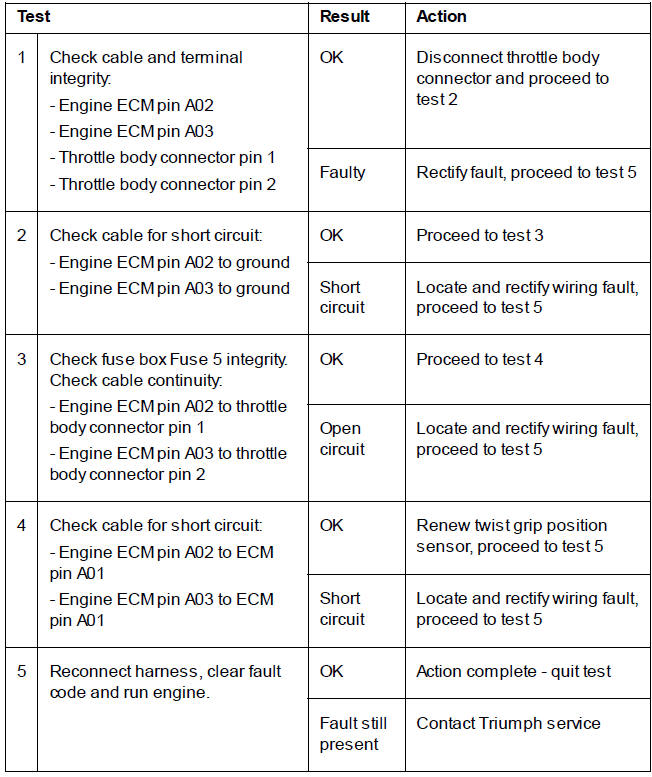
Pinpoint Tests
Circuit Diagram
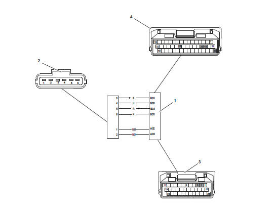
- Engine Electronic Control Module
- Throttle Body Connector
- Electronic Control Module - Connector A
- Electronic Control Module - Connector B
Fuel Tank - Installation
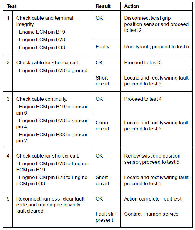
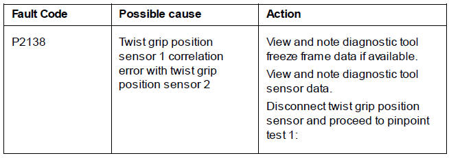
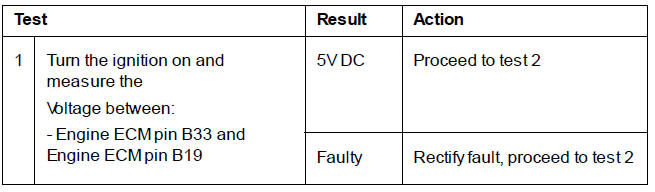
Pinpoint Tests
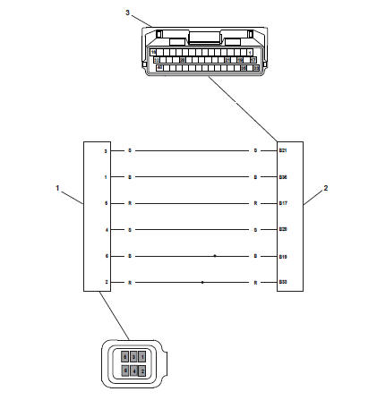
Circuit Diagram
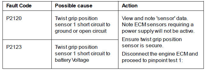
- Twist Grip Position Sensor
- Engine Electronic Control Module
- Electronic Control Module - Connector B
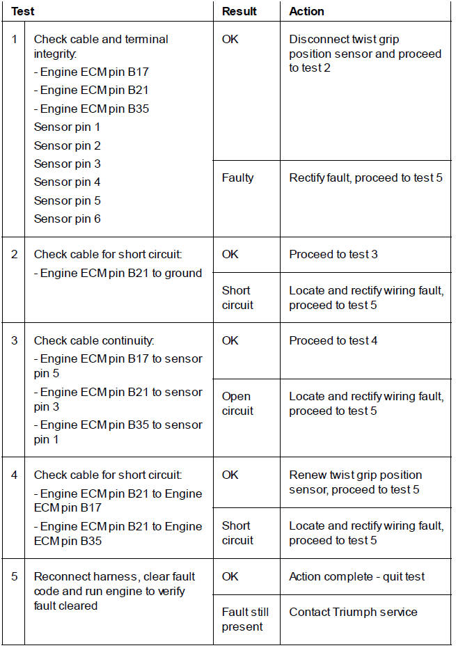
Pinpoint Tests
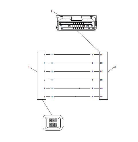
Circuit Diagram
- Twist Grip Position Sensor
- Engine Electronic Control Module
- Electronic Control Module - Connector B
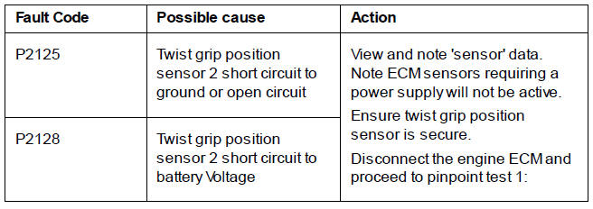
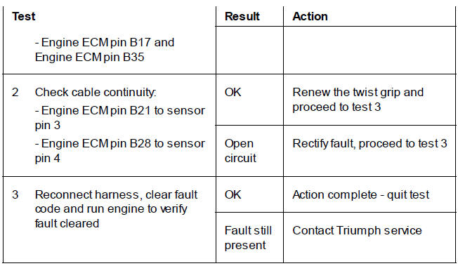
Pinpoint Tests
Circuit Diagram
- Twist Grip Position Sensor
- Engine Electronic Control Module
- Electronic Control Module - Connector B
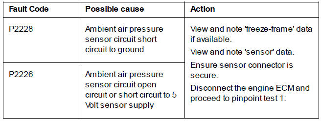
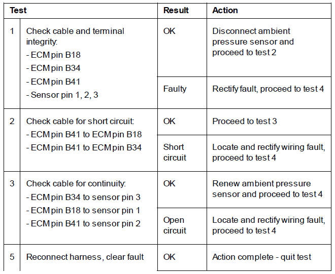
Pinpoint Tests
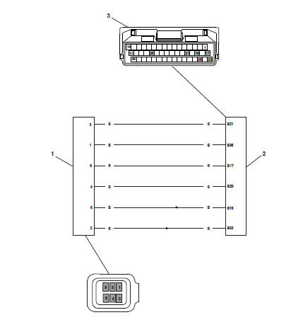
Circuit Diagram
- Ambient Air Pressure Sensor
- Engine Electronic Control Module
- Engine Electronic Control Module - Connector B
Fuel Pressure Checking
WARNING
Observe the warning advice given in the General Information section on the safe handling of fuel and fuel containers.
A fire, causing personal injury and damage to property could result from spilled fuel or fuel not handled or stored correctly.
WARNING
Before starting work, ensure the motorcycle is stabilised and adequately supported. This will help prevent it from falling and causing injury to the operator or damage to the motorcycle.
1. Open the fuel cap cover andremove the fuel cap.
Note
- Note that the chamfered edge of the plastic locking ring is uppermost for installation.
- Note the four locating lugs on the plastic locking ring that fit into the cut outs in the fuel tank filler neck.
2. Using a suitable proprietary lever, remove the plastic locking ring.
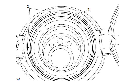
- Plastic locking ring
- Locating lug (2 shown)
3. Turn the fuel cap cover clockwise to release its four locating lugs from the fuel tank filler neck.
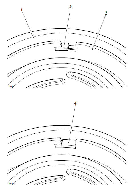
- Filler cap cover
- Fuel tank filler neck
- Locating lug in locked position
- Locating lug in open position
4. Carefully lift off the fuel cap cover.
WARNING
Observe the warning advice given in the General Information section on the safe handling of fuel and fuel containers.
A fire, causing personal injury and damage to property could result from spilled fuel or fuel not handled or stored correctly.
WARNING
Before starting work, ensure the motorcycle is stabilised and adequately supported. This will help prevent it from falling and causing injury to the operator or damage to the motorcycle.
Note
- Note that the chamfered edge of the plastic locking ring is uppermost as noted during removal.
- Note the four locating lugs on the plastic locking ring that fit into the cut outs in the fuel tank filler neck.
1. Position the fuel cap cover and then turn anticlockwise to lock its four locating lugs into the fuel tank filler neck.
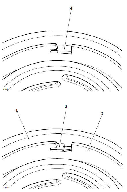
- Filler cap cover
- Fuel tank filler neck
- Locating lug in locked position
- Locating lug in open position
2. Refit the plastic locking ring. Ensure a positive click is felt on each locating lug when fitting the plastic locking ring.
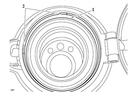
- Plastic locking ring
- Locating lug (2 shown)
3. Refit the fuel cap and check the operation of the lock
WARNING
Observe the warning advice given in the General Information section on the safe handling of fuel and fuel containers.
A fire, causing personal injury and damage to property could result from spilled fuel or fuel not handled or stored correctly.
Before starting work, ensure the motorcycle is stabilised and adequately supported. This will help prevent it from falling and causing injury to the operator or damage to the motorcycle.
Perform the following operations:
- Seat - Removal
- Battery - Removal
1. Remove the fixing securing the rear of the fuel tank to the frame. Discard the lock nut.
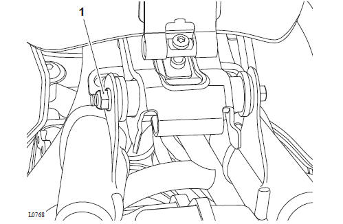
- Fixings
2. Pivot the fuel tank upwards at the rear.
3. Detach the breather hose from its retaining clips on the fuel tank then disconnect it from the fuel tank.
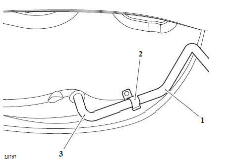
- Breather hose
- Retaining clips
- Fuel tank spigot
4. Disconnect the electrical connectors for the fuel pump and the fuel level sensor from the main harness.
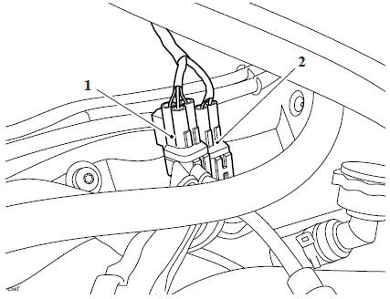
- Fuel level sensor electrical connector
- Fuel pump electrical connector
WARNING
If the fuel rail is dismantled without first reducing pressure, fuel may escape causing clothing and components to be coated with fuel.
This would represent a serious fire hazard which could lead to burn injuries and damage to property.
5. Temporarily reconnect the battery, positive (red) lead first and tighten the terminals to 4.5 Nm.
Note
- Because fuel stored in the fuel rail will be at 3.5 bar pressure, it is essential that the fuel pressure is reduced before any dismantling of the fuel rail takes place. To reduce pressure, briefly crank the engine with the fuel pump disconnected.
- When disconnected, the fuel tank is self-sealing but a small amount of fuel may dribble from the hose.
- To protect the components under the fuel tank, place suitable material over the components to absorb the small amount of fuel that may come from the fuel tank and its fuel lines.
6. Briefly crank the engine to reduce the fuel pressure in the fuel rail.
7. Disconnect the battery, negative (black) lead first.
8. To release the double check clip, ease the latch away from the connector until the release buttons are exposed.
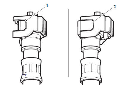
- Locked Position
- Unlocked Position
9. Disconnect the fuel hose by squeezing the sides of the connector and pulling the hose free from its spigot on the fuel pump rail. Collect any fuel remaining in the hose in a suitable container.
- Fuel hose
10. Detach the fuel pump and fuel level sensor electrical connectors from the ignition coil bracket.
11. Slide the tank rearwards to detach it from the frame.
12. Take care not to lose the front mounting and rear mounting rubbers. Renew any mounting rubber which shows signs of damage.
Fuel Pump Assembly - Removal
Fuel Pump Assembly - Inspection
Fuel Pump Assembly - Installation
Fuel Pressure Regulator - Removal
Fuel Pressure Regulator - Inspection
Fuel Pressure Regulator - Installation
Fuel Pump - Removal
Fuel Pump - Inspection
Fuel Pump - Installation
Fuel Level Sensor - Removal
WARNING
Observe the warning advice given in the General Information section on the safe handling of fuel and fuel containers.
A fire, causing personal injury and damage to property could result from spilled fuel or fuel not handled or stored correctly
WARNING
Before starting work, ensure the motorcycle is stabilised and adequately supported. This will help prevent it from falling and causing injury to the operator or damage to the motorcycle.
1. Ensure the front and rear mounting rubbers are correctly fitted.
2. Manoeuvre the tank into position, engaging it with the front mounting rubbers.
3. Reconnect the fuel feed hose by gently pushing inwards until the hose engages with a click.
- Fuel hose
4. Slide the double check latch to the locked position until the release buttons are covered. If the latch will not slide into position, then the fuel hose is not fully home on its spigot and must therefore be refitted correctly
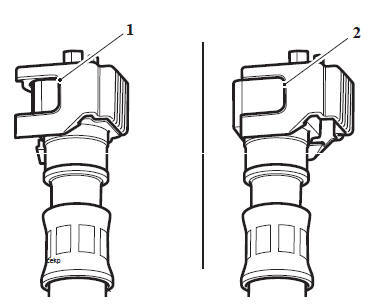
- Locked Position
- Unlocked Position
5. Attach and connect the breather pipe to the fuel tank.
6. Connect the electrical connectors for the fuel pump and the fuel level sensor to the main harness and attach them to the ignition coil bracket.
7. Lower the tank into position ensuring the breather pipe is not trapped, kinked or twisted.
8. Refit the rear fuel tank mounting retaining bolt.
9. Fit a new locknut, counterhold the bolt and tighten the new lock nut to 8 Nm.
10. If removed, use a proprietary professional automotive workshop equipment approved for fuel handling, to refill the fuel tank with any fuel removed earlier.
Perform the following operations: Perform the following operations:
- Battery - Installation
- Seat - Installation
Fuel Level Sensor Installation
Airbox - Removal
Airbox - Installation
Throttle Body and Inlet Manifold Assembly - Removal
Throttle Body and Inlet Manifold Assembly - Installation
WARNING
Observe the fuel handling precautions given in the General Information section.
Fuel pressure is checked using T3880001 - Fuel Pressure Gauge.
T3880001 - Fuel Pressure Gauge
Perform the following operations:
- Fuel Tank - Removal
1. Place the fuel tank on a suitable support, closeto the motorcycle.
2. Using the T3880391 - Fuel Pump Extension Cable, carefully connect the fuel pump connection on the main harness to the fuel tank.
3. Select the fuel pressure gauge adaptor marked 'A' from T3880001 - Fuel Pressure Gauge.
WARNING
Always use the correct fuel pressure gauge adaptor. Use of an incorrect adaptor will result in a fuel leak. A fuel leak can result in a fire causing damage to property and injury to persons.
4. Connect the adaptor hose to the fuel pump plate outlet and fuel hose as shown in the illustration below.
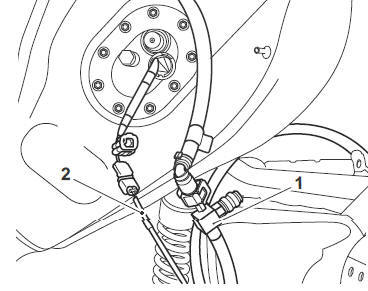
- Adaptor hose 'A'
- T3880391 - Fuel Pump Extension Cable
5. Connect the fuel pressure gauge to the adaptor hose as shown below by pushing the gauge spigot into the adaptor until a click can be heard.
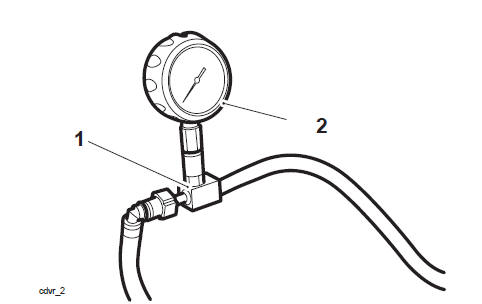
- Adaptor hose
- Fuel pressure gauge
Note
To release the fuel pressure gauge from the adaptor, slide the outer ferrule downwards. This will allow the gauge to spring upwards from the adaptor.
6. Ensure the gauge is visible to the side of the motorcycle.
7. If fuel has been removed from the fuel tank during removal, use a proprietary professional automotive workshop equipment approved for fuel handling, to add fuel to the tank with any fuel removed earlier.
8. Reconnect the battery, positive (red) lead first.
9. Start the engine and observe the fuel pressure reading on the gauge.
Note
- The fuel pressure should be 3.5 bar nominally.
10. When fuel pressure checking is complete, disconnect the battery, negative (black) lead first.
11. Disconnect the fuel pressure gauge adaptor and wiring extension. Collect any fuel in the hose in a suitable container.
Perform the following operations:
- Fuel Tank - Installation
See also:
 Triumph Scrambler 1200 XC - Service manual > Pinpoint Tests - Fuel
Oxygen Sensor Heater Pinpoint Tests
Triumph Scrambler 1200 XC - Service manual > Removal and Installation - Engine Management Components
WARNING Observe the warning advice given in the General Information section on the safe handling of fuel and fuel containers. A fire, causing personal injury and damage to property could result from spilled fuel or fuel not handled or stored correctly.
 Ducati Scrambler
 Fantic Caballero 500
 Indian FTR 1200
 Moto Guzzi V85 TT
 Royal Enfield Bullet Trials Works Replica
 Triumph Scrambler 1200 XE
 Triumph Street Scrambler
 Yamaha XSR700
 Ducati Scrambler 800
 Moto Guzzi V85 TT
 Triumph Scrambler 1200 XC