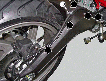
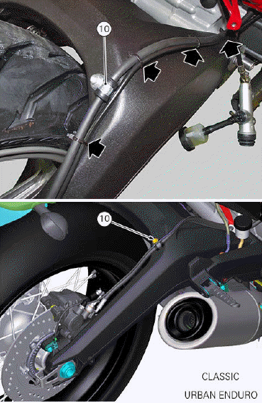
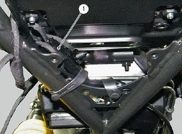
 Ducati Scrambler 800 - Service manual > Routing wiring harnesses/hoses
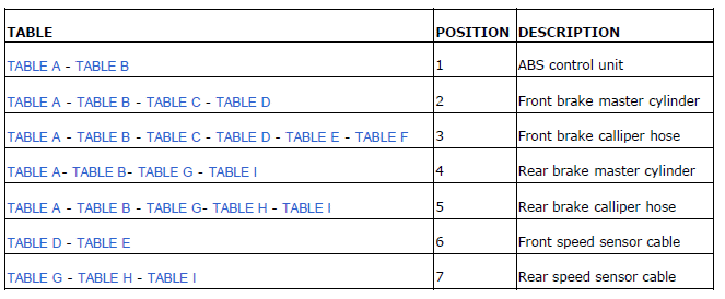
TABLE A
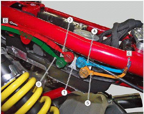
TABLE B
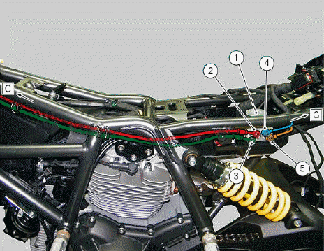
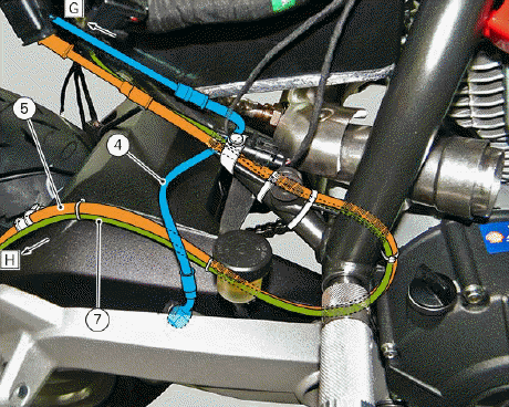
TABLE C
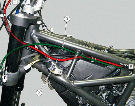
TABLE D
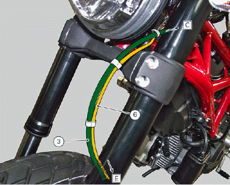
TABLE E
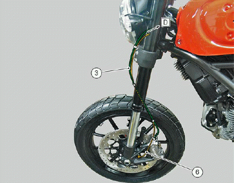
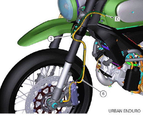
TABLE F
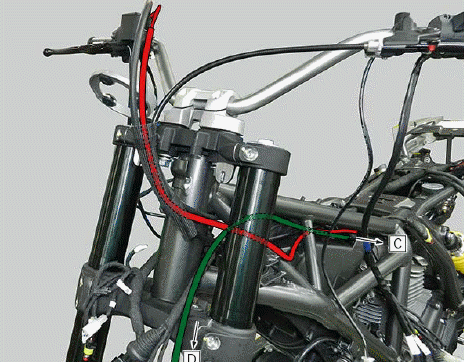
TABLE G
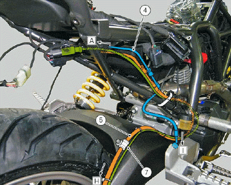
TABLE H
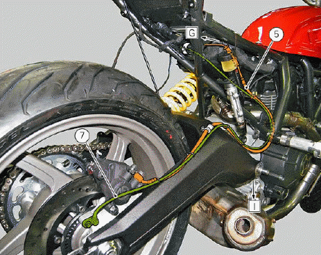
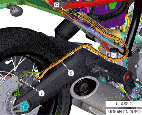
TABLE I
Refitting the ABS control unit
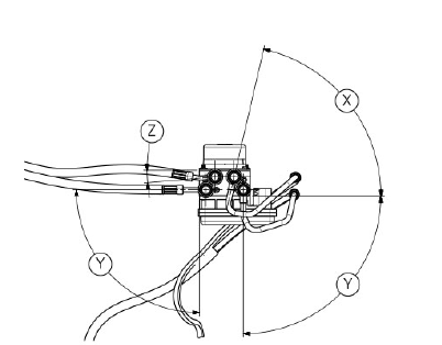
In case of replacement or removal of the hoses (3), (4), (5) and (6) on the ABS control unit, it is necessary to pay special attention to the union position on the control unit.
Warning If incorrectly positioned, hoses can affect brake operation and foul moving parts. Position the component as shown in the figure.
X=77Âş
Y=90Âş
Z=5Âş
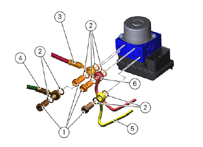
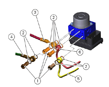
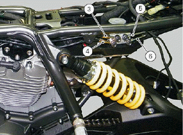
Hoses (3), (4), (5) and (6) must be secured in place using new sealing washers (2) on unions.
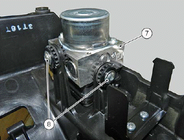
Fasten the ABS control unit (8) by tightening the screws to the torque of 6.8 Nm +- 10%.
Tighten screws (1) securing the hoses indicated below to the ABS control unit to a torque of 23 Nm +- 10%:
ABS control unit hose to front brake master cylinder (3);
ABS control unit hose to front brake calliper (4);
ABS control unit hose to rear brake master cylinder (5);
ABS control unit hose to front brake calliper (6).
Removing the ABS control unit
Remove the seat (Removing the seat).
Remove the fuel tank (Removing the fuel tank).
Remove the battery.
Remove the front brake system (Removing the front brake system).
Remove the rear brake system (Removing the complete rear brake control).
Loosen special screws (1), collect seals (2) and remove the following hoses:
(3) Front brake master cylinder;
(4) Front brake calliper;
(5) Rear brake master cylinder;
(6) Rear brake calliper.
Disconnect the connector (11).
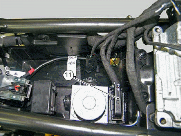
Remove the ABS control unit (7), loosening the two screws (8).
Release the two hoses (3) and (4) from cable ring (9).
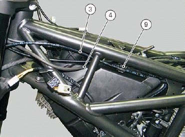
Release the brake hose (6) from the clip (10).
Changing the rear phonic wheel sensor
REMOVAL PROCEDURE
Disconnect connector (1) of rear ABS sensor from electric wiring. Open all clips retaining rear ABS sensor cable: refer to tables under Section "Routing wiring harnesses / hoses".
Remove the rear ABS sensor (2) from its seat on rear calliper holder plate (3), by loosening retaining screw (4) and collecting calibrated sealing washer (5). Check air gap between new rear ABS sensor (2) and rear phonic wheel as explained under: "Adjusting the AIR-GAP of phonic wheel sensor". Fasten the sensor to the calliper holder plate by tightening screw (4) to a torque of 7 Nm +-10%.

REFITTING PROCEDURE
Connect connector (1) to main wiring. Fasten all clips retaining rear ABS sensor cable: refer to tables under Section "Routing wiring harnesses / hoses".
See also:
 Ducati Scrambler 800 - Service manual > Changing the front phonic wheel sensor
REMOVAL PROCEDURE Disconnect front ABS sensor (2) connector (1) from main wiring.
 Ducati Scrambler
 Fantic Caballero 500
 Indian FTR 1200
 Moto Guzzi V85 TT
 Royal Enfield Bullet Trials Works Replica
 Triumph Scrambler 1200 XE
 Triumph Street Scrambler
 Yamaha XSR700
 Ducati Scrambler 800
 Moto Guzzi V85 TT
 Triumph Scrambler 1200 XC